Trying to find a service manual
In part one I looked at the problems, and could conclude that the ALC error I’m seeing is most likely generated in the 3Ghz module.
So I started searching for the Service manual, and the ones I could find have description on the working of the modules, but the schematic and part lists these descriptions refer to, are not included. Without schematics this is already complicated, but without part numbers, most likely impossible.
Most of the components are SMD, and their markings are not always very descriptive. For example: A09 is this a A with the number zero, or the capital letter “O” ? or a component with just H2 on it won’t help either.
While I was searching for a service manual I investigated the error even more, since the error manifest itself when the unit gets warmer.
So I let the unit run for quite some time, and quickly removed the 3Ghz module, so I could feel where most of the heat is generated. Since these spots are the most likely candidates.
Taking a look inside the 3Ghz module
At that point I was at the end of the troubleshooting I could do. So I started to disassemble the 3Ghz module. Which got a lot of screws. And this is also the first time I opened a RF module. And at first glimpse, these kind of PCB look intimidating. Some RF parts and arrangement looks like RF black magic. But at the end of the day, it’s just a bunch of SMD components, and some specific RF stuff. Which I hopefully don’t have to mess around with. I also noticed a scratch on the PCB, where the scratch is coming from I don’t know, but it looks like someone worked on this module before.
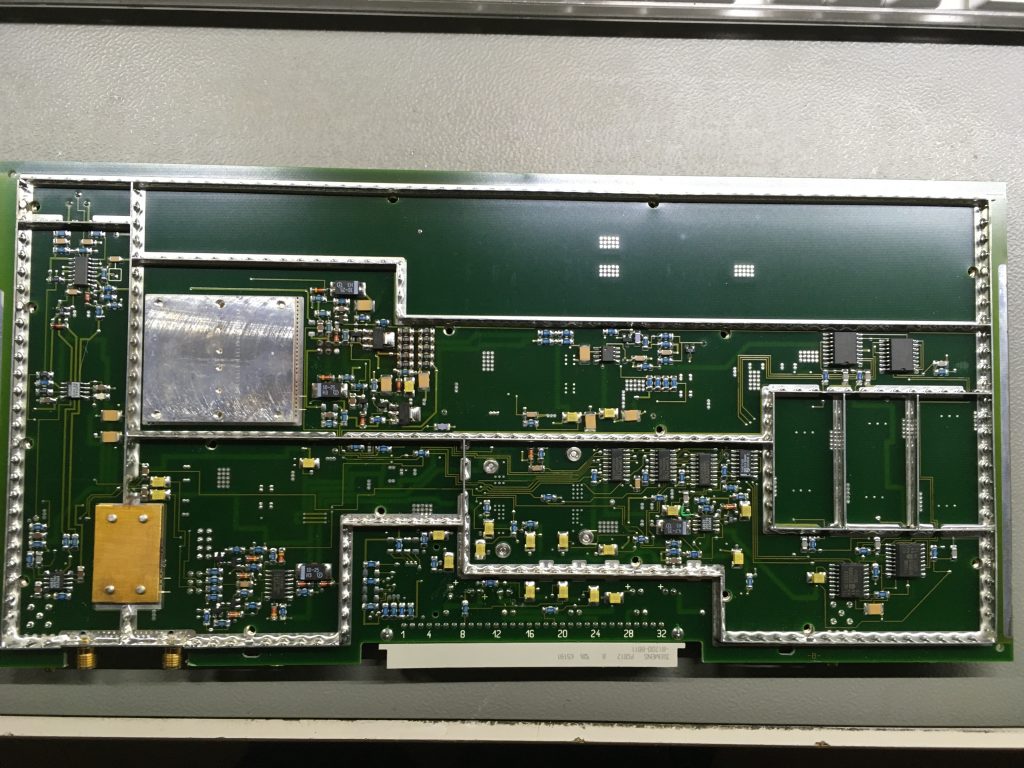
While I was studying the layout of the 3Ghz module I made a list of possible components which could be the problem. The ALC error tells me that the problems must be before the signal leaves the module. Once the signal leaves the module, there is no way of detecting the level of the signal.
So may first plan of attack was to replace every opamp in the signal path, closest to the connector where the signal would leave the module.
Finally I found the Service Manual for the R&S SMT03
While making the list, a kept on searching to find the service manual. And to my surprise I found [here] the service manual with schematics, and most importantly a list with components.
Once I had the service manual I also could read the the 3Ghz uses the top cover as a heat shield. And from my experience I already notices how hot the module could get. So Without any proper cooling I don’t want to run this module without any covers. Which complicates troubleshooting even more.
But I figured: Since I’m already on the path of “guessing” let’s continue with it. After studying the schematics, I picked a few places where the ALC error could come from.
Got it fixed
Long story short: I replaced all the opamps (which are 3 or 4) in the RF detection section, replaced 3 opamps in the 1.8Ghz filter range. And swap out some ceramic capacitors in the hot spots.
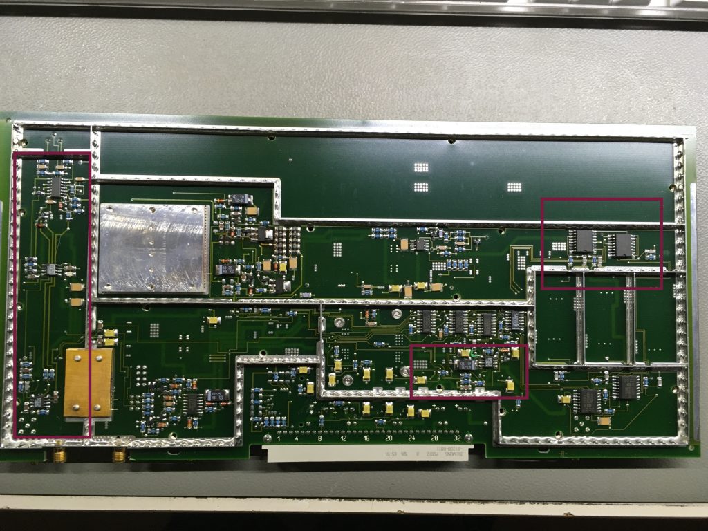
Of course, did didn’t solve the ALC error. After studying the schematics more, the only place could be the amplifier or pre-amplifier section.
While going ever the PCB I noticed someone replaced a component, since there was a lot of residue left. And this confirms that someone had worked on this module before. Was this also the person cause the scratch on the PCB ?
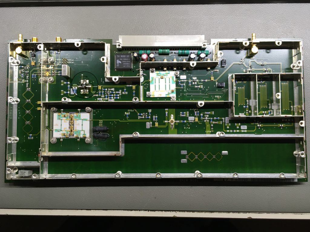
The component “A09” is on the other side of the module: This component turns out the be a “Hewlett Packard MSA-0986 Silicon Bipolar MMIC Amplifier”
This part is not easy to get, but I did mange to find it on Ebay. And as soon as it arrived, I replaced this part. And I could clean up most of all the residue.
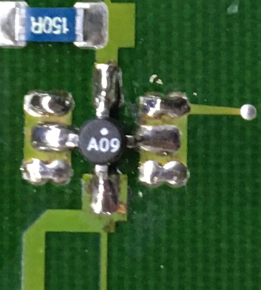
As it And as it turns out, this part was the cause of the ALC error. I let the unit run for a couple of hours (fully assembled, so with all the covers on) and the error was gone.
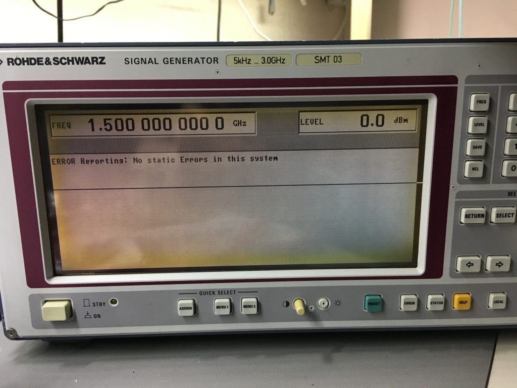
While this is not my preferred way of fixing It payed of in the end. Mainly because I could pin point the problem to a specific module, and I notices the work of someone else.
This brings me to another point: Lately I noticed on Ebay that prices has gone up for second hand , broken equipment. A R&S SMT03 with a lot of problems still cost over $500 or even $700 dollars. Fixing these units without a proper service kit is very hard to do. Especially if like me, lacking RF skills. For a trained electronics engineer, it’s more easy. I think I just got luckily. But beware of units like this, and their (hidden) problems.
I love how you turned this into a kind of detective story. It was fun to read. I hope you write more like this, and even publish a book, someday.
Thank you for much the complement. When I got something to repair, I’ll try to write it in a similar fashion.