Time to say goodbye to Apple ?

Introduction

I’m a long term user of Apple products. My first Apple computer was a white Imac, and I loved it. The second Imac is a 21.5-inch, Late 2013 (model iMac14,1). And I’m still using this Imac with great pleasure. The main reason for using Imac is of course MacOS. The reason is simple: The OS is consistent, user friendly. Which result in a OS that allows me to be productive. Of course, this is personal opinion. Not to start a flame war. I’m a strong believer of choosing the tool that fits you best.

So why do I feel that the time has come to say goodbye to Apple ? Well, it all has to do with what I stand for. I strongly believe in the right to repair, being owner of your own hardware, and the way I think about sustainability. And Apple doesn’t seem to care about these points…

An Imac is getting old, time to look around for a new one

The Imac I’m currently using everyday is working just fine. A few years back I replaced the hard drive with a SSD drive, and upgrade the RAM memory to 8Gb. This Imac runs the last supported MacOS version Catalina (macOS 10.15). However this OS is no longer supported by Apple, and so a lot of Applications are also lacking behind. For example Fusion 360 which I use a lot, will stop working on august this year (2023). Homebrew which I use a lot for my work keep complaining it no longer supports this OS, and the X code it apparently needs to function properly. Docker stopped working.. and the lists goes on.

While the hardware is still capable I started to look around for a new Imac or Mac mini, and curious about the new M1 or M2 chip, I dived into the hardware architecture. And that’s where I hit a roadblock..

Do you own your data ?

To start off, I know that the later (2020?) Imacs got no replaceable hard drives any more. Drives are soldered onto the motherboard, and are tricky to replace. I know it’s possible with these Intel Imac’s to wipe a few IC’s of the motherboard, get a custom made PCB and replace the onboard flash IC’s (NANDs) with M.2 SSD drive. And yes I could to that. I know how to desolder BGA’s , and even how to re-ball them, and all that kind of jazz. But really ? Soldering drives onto a motherboard, so you can’t replace a drive easily? Data Recovery ?? Apple says no…

But it gets worse.. With the new M1 or M2 chip, the drives are still soldered on the motherboard, but due to Apple not wanting you to repair architecture change, the firmware of the NAND IC’s now depends on the size of the storage. So for example a 512Gb drive, has different firmware then a 1Tb drive. That’s not the worse part. The worse part is that Apple uses some kind of raid 0. It means that if one of the NAND IC’s feels.. you lose all data. Yep… And recovery ? Apple says no…

(Well there is a way of replacing these NAND drives.. get NAND drives from a MAC Studio Pro for hundreds of dollars, de-solder them, re-ball the BGA’s. Re-flash the firmware with a specialized tool, solder them back onto the motherboard, and you’re good to go..)

So pay attention when buying a “refurbished” Imac with a M1 or M2 chip.. These NAND devices has a certain amount of R/W cycles.. So sooner then later your Mac will fail, beyond (easy) repair..

Why Apple, why ?

Apple seems to be obsessed by making their devices smaller, and smaller. The claim for example that the new Imac are thinner because of the M1 chip. is bullshit. They left out the power supply, so now you need to use a power adapter. Besides the size, Apple seems to be obsessed by controlling their hardware.  Soldering drives onto the motherboard, instead of using the small M.2 drives ? In my mind there is no reason to make it almost impossible to change out hard drives.

It goes against my feeling of having the right to repair the hardware I own. Making hard drives replaceable, or upgradeable, memory, and god forbid the CPU upgradeable means that hardware lives longer, less landfill, less usage of resources, a greener world and the rest of it. But no… Apple doesn’t want that. Apple wants total control of their hardware. Apple doesn’t want you to repair your hardware. Apple isn’t interested hardware which has a long life.

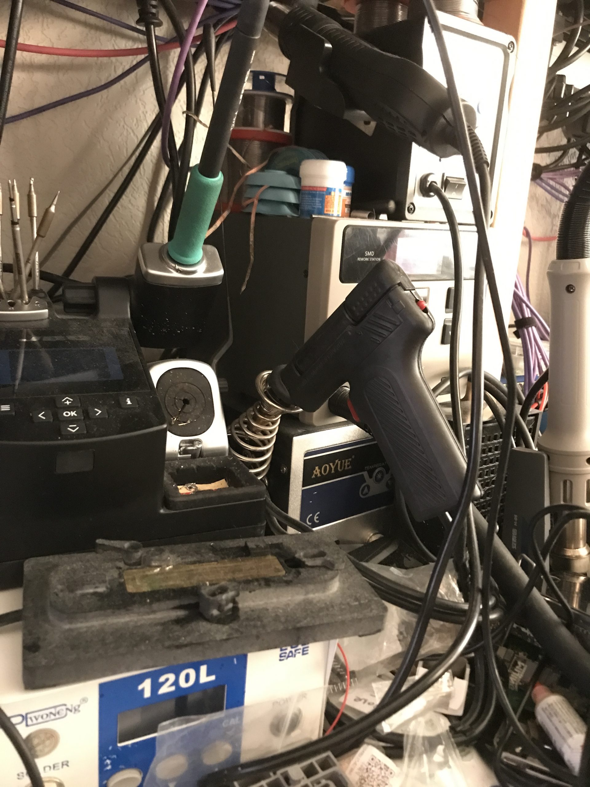
And yes I have experience in repairing Apple hardware. I repaired Iphones, (But also Nokia, Sony). From Apple I learned the hard way you can’t simply swap out an IC, because it’s serialized onto the motherboard. And yes.. swapping out an IC seems extreme?  Well try to swap your battery then…. or your screen for that matter.

The point is: Apple uses a proprietary method to reprogram these serialized parts, which only “authorised dealers” can access. And not you.. Yes you .. the person who bought the hardware, and have to illusion that you own your hardware, and data for that matter.

And yes.. Apple got this “repair program” which is one big marketing bullshit in my opinion. You can rent the hardware needed to replace a screen. After replacing the screen, you have to call Apple, submit to their will (read you have to give up your privacy) and Apple reprograms the serialized part on your phone.

Nice rant up to now..
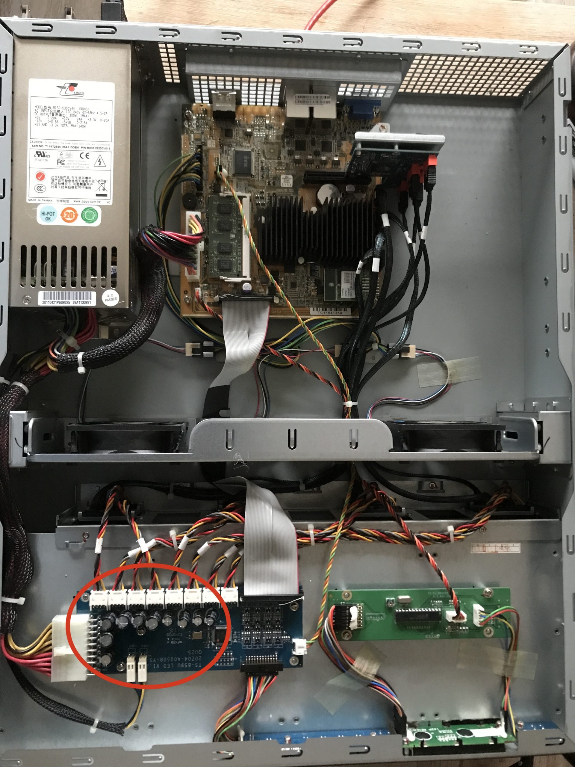
Yes, I know. But if I forget about the whole proprietary stuff, and owning your hardware thing, I still can’t find a reason why I should buy expensive hardware. And by expensive hardware I mean hardware with limited life span. If I need to spend a couple of thousand of euro’s for a “state of the art” piece of hardware, I rather now by off the shelf hardware, and build an own PC, which lasts for at least 10 years or more. And yes I did that more then once. For example this pc I build in 2012 still runs and is used every day.

And while it maybe is a rant up till now, on the other hand, coming to this conclusion is hard. Like I said in the introduction, I really like Apple products for their style, the ease of use. The idea of not be able to use macOS makes me sad. The idea of using alternatives like Windows doesn’t make me happy… (and that’s an understatement) What about Linux… it gives you all the freedom you need.. yes, but I got a job to be done, and don’t want to mess around with inconsistent GUI’s and add-ons.. But maybe.. just maybe I’m able to experiment and use this. (While I keep in mind that Apple at one point says goodbye to Intel hardware, and only is going to support their M1 and M2 chips.)

To postpone this decision and give my beloved Imac some more years, I managed to upgrade to Monterey by using OpenCore Legacy Patcher.  So it’s possible to give your “old” Apple hardware more years…

Fixing Qnap TS-859U+

Introduction

The Qnap TS-859U+ is an old system, which I’m being using for years and years now. It never gave me any problems, being an reliable friend, until….

Disaster strikes

Yes.. anyone which does something with storage would tell you: “It’s not the question if a drive fails, the question is when the drive going to fail”. Maybe this sounds a bit cheesy, but it’s true. Therefore using RAID may prevent data loss, when a disk fails. Of course, this means a RAID set which brings redundancy. In this case the NAS can hold 8 disks. And I use 2x RAID 5 set, so 2×4 Disk in two RAID 5 sets. However, a RAID set is not a replacement, or substitute for backups.

In a RAID 5 set 1 drive can fail, and everything is still alright. The idea is when the bad disk is replaced, the RAID 5 set recovers, and everything is o.k. Well anyone with enough experience knows that rebuilding a RAID set (5 or 6) puts stress on the remaining disks. This brings the danger of a second disk failing during rebuild. Therefore, having a backup is a must, if you care about your data.

The problem with backups is (and it depends on how you make the backup) is that a incomplete backup, is no backup. So with this being said, let’s take a look what happened..

Ignoring a warning sign… not smart

These QNAP have one feature which is really useful, as long as it’s not being ignored, and that sounding a loud beep when something important is happing, like a disk failure. In the middle of a night I woke up, because I thought I heard a beep, listing for a few moments I didn’t hear anything else alarming, and got back to sleep, and forgot about it in the morning.

In the afternoon I noticed that the Qnap was reacting very slow.. It took ages before the user interface was loading. So it walked over to the QNAP, which is in other room, and I noticed 2 red lights on two disk in the same RAID 5 array set. Not good.

Thinking back, this was what I heard at night.. the QNAP was trying to warn me something bad was happening. To make things worse.. the backup hadn’t run…

An unpleasant situation

At this point I didn’t want to reboot the Qnap, not sure how it would boot up, and if I still got the data on this RAID 5 set. So I managed to log into the CLI, which is just a Linux shell, and started to stop every service I don’t need. At this time I could also tell that the data is still there, but that one disk was “ejected” and one disk was in a “unhealthy status”

After stopping the services, which I did to lower disk activity, and to give the CPU some less load, I started to think about a rescue plan…

The rescue plan

The first thing was trying to trigger a rebuild of the array, by replacing the ejected disk. And that is where the fun really started. After a while a new disk was marked as “bad”. So I swapped this new disk to another QNAP, which is almost the same, and the disk was just fine. Swapped the disk back, and after some period of time.. the disk was marked as bad. So the only thing I could think of, is that the slot in the QNAP itself had a problem. This put me in a rough spot, since I now have a RAID 5 set, which only 3 drives, and one of them is on the point of giving up the ghost. And at that point I realized that no matter what, I’m going to loose data. At the end I got all the important data of the array, and some data I couldn’t care about. But for bringing an RAID 5 array a fix is needed..

What could be wrong with the drive bay?

Thinking about the possible reason why a drive is marked bad after some period of time, I considered the following: The SATA logic is working, so chances are, the IC’s etc. are all fine. The most likely issue is a bad power line. This could be a power supply issue or just the power line of the drive bay itself. Since only one drive is having this problem, I don’t think it’s a power supply problem. Most likely it’s one or more a capacitors which is the root cause.

Finally fixing the QNAP’s drive problem

After taking the QNAP out the server rack, and remove the top cover from the QNAP, I noticed that all the drives are connected to some what looks like a power distribution board, with a lot of caps on them. All the connections to this board where nicely labelled. So I took the capacitors of the board in the area of connector “4” and tested the caps. And they where low in capacitance, so I decided to replace all the caps on the board. After putting everything together again I started testing with drive bay 4 ,and yes! it worked again. And hopefully this QNAP will continue to run reliable for quite some years to come.


Cheap and low power network switches.. are they any good ?

Introduction

With higher energy costs, running a lab with network gear becomes a costly hobby. To keep costs down I decided to look at some cheaper switches, which low power consumption. While on that path, it would be very nice if the switches are fanless as well. Less noise. Which is good. The switches must be rack mountable.

The only problem is: I really don’t like the cheap Netgear, TP-LINK and Zyxel switches. I “grew up” with Extreme Networks , Foundry, Cisco and Allied Telesys switches. And yes, I don’t come close to HP switches, or 3Com switches for that matter. The time I had to deal with those, I always find them troublesome, and very user unfriendly. Well I digress, back to the subject at hand 🙂

I decided to buy the following three switches:

    • TP-Link TL-SG1016DE 16-Ports Gigabit Switch
    • Zyxel GS1900-24 24 + 2x SFP ports Gigabit switch
    • Zyxel XGS1930-28 24 1Gb 4x sfp+ 1/10Gb ports switch

The TP-Link switch is around 60 Euro’s, while the Zyxel GS1900 switch is around 100 Euro’s. The Zyxel XGS1930 is more expensive, since it’s a 10Gb capable switch, and comes around 360 euro’s which is still cheap, compared to Cisco, Extreme or Foundry switches.

Before diving into the switches, keep in mind this isn’t a review, and the article contains my (less then soft) opinions. And while I don’t like these low end switches it’s time to get out of my comfert zone, and see if I can make friends with these switches, and yes.. that won’t be easy 😉

The TP-Link TL-SG1016DE 16-Poorts Gigabit Switch

The first switch I had a look at is the TP-Link switch. And well, it works. It power usage is around 12Watt or so, and yes it’s fanless. It’s a small switch with a metal body. Which makes it more robust. The switch supports up to 32 dot1.q vlans, and has some other features as well. The main purpose for my use it to power my extensible Raspberry PI Cluster. If the switch is working reliable I might consider to buy a second one, so I can use it to connect my APC PDU’s to it.

After running the switch for months, it seems to do the business. For simple task this switch is usable. The main drawback is the lack of a way to list the mac address table. So In a real production network I won’t consider using this switch as a main switch. For a stub switch it might be ok.

The Zyxel GS1900-24

The (max) power consumption of this switch is 17.1 Watts according to the data-sheet. When first configuring the switch I stumbled across how Zyxel approaches vlan implementation. In one word: horrible. For example a trunk is used to “allow all unknown vlan’s to the switch to pass”. Which makes my skin crawl. In a serious network I NEVER want “unknown” vlans to pass between switches. Yeah sure.. it makes configuring links between switches so much easier… In my opinion: very bad practise, In a network configure things explicit, and don’t let devices do the configuration for you.

However, it’s possible to configure a port to accept “all”, and leave trunk disabled. Which means: accept only configured untagged and tagged frames on a port.

Apart from the vlan implementation, the web GUI interface is not that bad. The switch has a CLI, but it’s useless. You can’t configure the switch from the CLI. The CLI has a few commands available. Which makes me wonder why Zyxel puts any effort in supplying a CLI in the first place.

Another nice thing is that it’s possible to configure the management on a vlan interface. This also means that there is no need to have a untagged management vlan between switches. (I used to say: no untagged vlans on trunked ports, but .. well yeah..)

The only problem I had with this switch is when changing a port description, the port went down for a brief moment, but long enough to cause traffic interruption. In the latest firmware this issue is finally fixed.

Zyxel XGS1930-28

This switch is like all the previous switches fanless. The (max) power consumption of this switch is 24.6 Watts which is very low. When I booted the switch and logged into the GUI I was expecting an interface like the GS1900, but that was a disappointment. The vlan implementation is even worse. The trunk port foolish is the same, however to mark a port in a vlan as untagged, the option “Tx tagging” must be unset. Also to configure a vlan, this must be set to “Fixed”. The other option “Normal” is when using GVRP (Don’t use that… ) And the VLANID is now called “Vlan Group ID”..

Then there is the need to set a PVID (Port Vlan ID) on the port (untagged vlan) is poor software design (again in my opinion). And all the previous switches have this setting. The problem is that when not setting a PVID will set it to a default (vlan 1) which is bad, very bad. Vlan 1 shouldn’t be used a a regular vlan in a network.

In the “real” world a trunk port is configured with “untagged vlan none” for example, to prevent any untagged vlan (untagged ethernet frame) between switches. An access port is configured as “switchport access vlan vlanid”.

And the overall navigation in the GUI interface is not that good as the GS1900. It actually sucks in my opinion. For example: to configure a vlan, there are two sections to configure: “Static vlan Setup”and “Vlan Port Setup”. It’s not the end of the world, but having consistent interface layout between models would be nice. Of course in the end you get used to the user interface, but it doesn’t bring a smile on my face, while using it.

Like the GS1900, on this switch it’s also possible to configure the management interface as a vlan interface. Which is very neat.

This switch can also be configured by using the Zyxel’s clound “Nebula Control Centre (NCC). Which maybe the reason the user interface is different.  In my mind, using a cloud to configure your network is the best thing to do:  from a security point of view, and definitely from a continuity point of view (what happens when the Internet connection goes down, and you must remotely access your switches to configure them?

And yes this switch also has a CLI. There are more commands, but it’s not possible to configure the switch through this CLI. If it was possible to configure the switch through this CLI would add a lot of value to the switch.

The main reason for bying this switch is that it has four SFP+ ports, which can be used for SFP’s (1Gb) and SFP+ (1oGb). That gives this switch flexibility and a cheap way to add 10Gb to the network. Another benefit might be that the switch has basic layer 3 capabilities. I don’t know what the throughput when routing packets, but it adds more flexibility.

Overall conclusion

As a network engineer being used to work in ISP backbones and core networks I won’t like to see these switches. In a small business I guess it’s okay. However the TCO of these switches might be higher since real remote automation is not really possible.  The different GUI interfaces on the switches add to this. I guess if you don’t have any network knowledge, and going with to vlan implementation how Zyxel see it, might make it more easy to understand.  Enough over the dot1q vlan implementation details.

I use this switches for quite some time now, and they just work without any problems. The only rare problem I had that a Zyxel 19oo switch messed up it’s mac table. I saw mac addresses in vlan’s where they didn’t belong. Which messed up the mac addresses table on other switches as well. I “solved” that by rebooting the switch.  And making sure that vlan 1 was not configured on any used port. After this one time, it didn’t happen again.

A good question will be: Is it fair to compare these switches to enterprise switches ?

I guess not really when looking at the the price tag. When looking at the Zyxel switches and there feature set: then yes… maybe ? However performance wise.. I wouldn’t dare to compare.

If you look at these switches for what they are: for small business, and low power, the Zyxel switches provide a rich feature set, and are reliable. The TP-Link switch is the cheapest switch, and makes it ideal for a stub switch, and is also reliable. The real downside is not having the ability to view / clear the mac address table (at least I couldn’t find it).

What surprised me with Zyxel is the good documentation, and even links from the user interface to the Zyxel comunity forum. Good documentation, and having a community is a big plus.

The Zyxel GS1900 I really can recommand, if a 1Gb switch fits the bill. The switch is reliable, packs a lot of features, and the user web interface is easy to navigate, and very usable.

The Zyxel GS1930-28 strong points are the 4 SFP+ plus ports, the user interface is somewhat disappointing. But like the GS1900 it’s a capable switch, which brings a lot of features, and cheap way to 10Gig.

So in the end: yes these switches help to keep the costs down, by using less power. They work well, and in my lab I don’t need the horse power of Enterprise switches which consumes several hundreds of Watts. However from time to time I miss the the robust cli’s of the Cisco and alike switches, and the capabilities to automate stuff.


Ethernet Ring Protection Switching (G.8032) with Juniper and Cisco

Introduction

The Juniper and Cisco lab used.

In this article we take a look at how to configure an Ethernet Ring Protection Switching (ERPS) between a Cisco ASR 903 and two Juniper MX series routers (a MX 104 and MX 80). This article only shows how to configure the nodes. There are enough articles on the web to explain how ERPS (or G.8032) works.

Topology

To configure ERPS a minimal of three devices  are needed. To have two extra routers to test end-to-end connectivity two logic systems are created on the Juniper routers. The topology looks like:

Topology, click for larger picture, opens in a new tab.

Configure the RPL owner (node1)

To configuration of the RPL owner, the interfaces are configured first:

set interfaces xe-2/0/0 description "Connection to ASR903 gi-0/0/1"
set interfaces xe-2/0/0 vlan-tagging
set interfaces xe-2/0/0 encapsulation flexible-ethernet-services
set interfaces xe-2/0/0 unit 1 family bridge interface-mode trunk
set interfaces xe-2/0/0 unit 1 family bridge vlan-id-list 100-1000
set interfaces xe-2/0/1 description "Connection to mx80 xe-0/0/0"
set interfaces xe-2/0/1 vlan-tagging
set interfaces xe-2/0/1 encapsulation flexible-ethernet-services
set interfaces xe-2/0/1 unit 1 family bridge interface-mode trunk
set interfaces xe-2/0/1 unit 1 family bridge vlan-id-list 100-1000

Next the protection group is configured:

set protocols protection-group ethernet-ring pg101 node-id 00:01:01:00:00:01
set protocols protection-group ethernet-ring pg101 ring-protection-link-owner
set protocols protection-group ethernet-ring pg101 east-interface control-channel vlan 100
set protocols protection-group ethernet-ring pg101 east-interface control-channel xe-2/0/1.1
set protocols protection-group ethernet-ring pg101 east-interface ring-protection-link-end
set protocols protection-group ethernet-ring pg101 west-interface control-channel vlan 100
set protocols protection-group ethernet-ring pg101 west-interface control-channel xe-2/0/0.1
set protocols protection-group ethernet-ring pg101 data-channel vlan 200
set protocols protection-group ethernet-ring pg101 data-channel vlan 300

Next the virtual switch is configured:

set routing-instances vs instance-type virtual-switch
set routing-instances vs interface xe-2/0/0.1
set routing-instances vs interface xe-2/0/1.1
set routing-instances vs interface xe-2/0/2.200
set routing-instances vs bridge-domains bd1 vlan-id 100
set routing-instances vs bridge-domains bd200 vlan-id 200
set routing-instances vs bridge-domains bd300 vlan-id 300

The configuration of the logical system is as follows:

The physical interface is a back-to-back connection to another physical interface on the same router:

set interfaces xe-2/0/3 description "Back-to-back connection to xe-2/0/2"
set interfaces xe-2/0/3 vlan-tagging
set interfaces xe-2/0/3 encapsulation flexible-ethernet-services
set interfaces xe-2/0/3 gigether-options auto-negotiation
set logical-systems LS1 interfaces xe-2/0/3 unit 200 vlan-id 200
set logical-systems LS1 interfaces xe-2/0/3 unit 200 family inet address 10.8.8.1/24

Configuration of Node2

The configuration is almost similar, except there can only be one RPL owner in the ring. So this node is configured as a normal node.

The ring interfaces are configured first:

set interfaces xe-0/0/0 description "Connection to mx104 xe-20/0/1"
set interfaces xe-0/0/0 vlan-tagging
set interfaces xe-0/0/0 encapsulation flexible-ethernet-services
set interfaces xe-0/0/0 unit 1 family bridge interface-mode trunk
set interfaces xe-0/0/0 unit 1 family bridge vlan-id-list 100-1000
set interfaces ge-1/0/0 description "Connection to ASR903 gi-0/0/0"
set interfaces ge-1/0/0 vlan-tagging
set interfaces ge-1/0/0 encapsulation flexible-ethernet-services
set interfaces ge-1/0/0 unit 1 family bridge interface-mode trunk
set interfaces ge-1/0/0 unit 1 family bridge vlan-id-list 100-1000

The configuration of the protection group is as follows:

set protocols protection-group ethernet-ring pg102 east-interface control-channel vlan 100
set protocols protection-group ethernet-ring pg102 east-interface control-channel ge-1/0/0.1
set protocols protection-group ethernet-ring pg102 west-interface control-channel vlan 100
set protocols protection-group ethernet-ring pg102 west-interface control-channel xe-0/0/0.1
set protocols protection-group ethernet-ring pg102 data-channel vlan 200
set protocols protection-group ethernet-ring pg102 data-channel vlan 300

The configuration of the virtual switch:

set routing-instances vs instance-type virtual-switch
set routing-instances vs interface xe-0/0/0.1
set routing-instances vs interface xe-0/0/2.200
set routing-instances vs interface ge-1/0/0.1
set routing-instances vs bridge-domains bd1 vlan-id 100
set routing-instances vs bridge-domains bd200 vlan-id 200
set routing-instances vs bridge-domains bd300 vlan-id 300

The logical system configuration on this node, needs two physical interfaces. To achieve this, the interfaces xe-0/0/1 and xe-0/0/2 are connected back-to-back:

set interfaces xe-0/0/1 description "Back to back connection to xe-0/0/2"
set interfaces xe-0/0/1 vlan-tagging
set interfaces xe-0/0/1 encapsulation flexible-ethernet-services
set interfaces xe-0/0/2 description "Back to back connection to xe-0/0/1"
set interfaces xe-0/0/2 vlan-tagging
set interfaces xe-0/0/2 encapsulation flexible-ethernet-services
set interfaces xe-0/0/2 unit 200 family bridge interface-mode trunk
set interfaces xe-0/0/2 unit 200 family bridge vlan-id-list 200

The logical system is configured as:

set logical-systems LS1 interfaces xe-0/0/1 unit 200 vlan-id 200
set logical-systems LS1 interfaces xe-0/0/1 unit 200 family inet address 10.8.8.2/24

The configuration of node3 (Cisco ASR903)

The configuration start with configuring the g8032 part:

ethernet cfm ieee
ethernet cfm global
ethernet cfm domain g8032_domain level 0
service g8032_domain evc evc_name vlan 100 direction down
continuity-check
continuity-check interval 3.3ms
!
!
ethernet ring g8032 profile g8032_profile
 timer wtr 1
!
ethernet ring g8032 g8032_ring
 port0 interface GigabitEthernet0/0/1
 port1 interface GigabitEthernet0/0/0
 instance 1
  profile g8032_profile
 inclusion-list vlan-ids 100,150-2999
 aps-channel
  level 0
  port0 service instance 1
  port1 service instance 1
  !
 !
!
ethernet evc evc_name
!

Next configure the bridge domains:

bridge-domain 100
bridge-domain 200
bridge-domain 300

Next the ring interfaces are configured:

!
interface GigabitEthernet0/0/0
 no ip address
 negotiation auto
 service instance 1 ethernet evc_name
 encapsulation dot1q 100
 bridge-domain 100
 cfm mep domain g8032_domain mpid 2
  continuity-check static rmep
  rmep mpid 1
!
service instance trunk 1000 ethernet
 encapsulation dot1q 150-2999
 rewrite ingress tag pop 1 symmetric
 bridge-domain from-encapsulation
 !
!
interface GigabitEthernet0/0/1
 no ip address
 negotiation auto
 service instance 1 ethernet evc_name
 encapsulation dot1q 100
 bridge-domain 100
  cfm mep domain g8032_domain mpid 1
   continuity-check static rmep
   rmep mpid 2
!
service instance trunk 1000 ethernet
 encapsulation dot1q 150-2999
 rewrite ingress tag pop 1 symmetric
 bridge-domain from-encapsulation
 !
!

Verifying the configuration

On the node1 use the following commands to verify if the ring is working:

show protection-group ethernet-ring configuration

Ethernet Ring configuration information for protection group pg101

G8032 Compatibility Version : 2
East interface (interface 0) : xe-2/0/1.1
West interface (interface 1) : xe-2/0/0.1
Restore interval : 5 minutes
Wait to Block interval : 5 seconds
Guard interval : 500 ms
Hold off interval : 0 ms
Node ID : 00:01:01:00:00:01
Ring ID (1 ... 239) : 1
Node role (normal/rpl-owner/rpl-neighbour) : rpl-owner
Node RPL end : east-port
Revertive mode of operation : 1
RAPS Tx Dot1p priority (0 .. 7) : 0
Node type (normal/open/interconnection) : Normal
Control Vlan : 100
Physical Ring : No
Data Channel Vlan(s) : 200,300

Next check the ring aps status:

run show protection-group ethernet-ring aps
Ethernet Ring Request/state RPL Blocked No Flush BPR Originator Remote Node ID
pg101 NR Yes No 0 Yes NA

Perform the same commands on node2:

show protection-group ethernet-ring configuration

Ethernet Ring configuration information for protection group pg102

G8032 Compatibility Version : 2
East interface (interface 0) : ge-1/0/0.1
West interface (interface 1) : xe-0/0/0.1
Restore interval : 5 minutes
Wait to Block interval : 5 seconds
Guard interval : 500 ms
Hold off interval : 0 ms
Node ID : A8:D0:E5:59:4E:E8
Ring ID (1 ... 239) : 1
Node role (normal/rpl-owner/rpl-neighbour) : normal
Revertive mode of operation : 1
RAPS Tx Dot1p priority (0 .. 7) : 0
Node type (normal/open/interconnection) : Normal
Control Vlan : 100
Physical Ring : No
Data Channel Vlan(s) : 200,300
run show protection-group ethernet-ring aps
Ethernet Ring Request/state RPL Blocked No Flush BPR Originator Remote Node ID
pg102 NR Yes No 0 No 00:01:01:00:00:01

On node3:

show ethernet ring g8032 configuration

Ethernet ring g8032_ring
Port0: GigabitEthernet0/0/1 (Monitor: GigabitEthernet0/0/1)
Port1: GigabitEthernet0/0/0 (Monitor: GigabitEthernet0/0/0)
Exclusion-list VLAN IDs:
Open-ring: no
Instance 1
Description:
Profile: g8032_profile
RPL:
Inclusion-list VLAN IDs: 100,150-2999
APS channel
Level: 0
Port0: Service Instance 1
Port1: Service Instance 1
State: configuration resolved

Next check the status:

show ethernet ring g8032 status
Ethernet ring g8032_ring instance 1 is Normal Node node in Idle State
Port0: GigabitEthernet0/0/1 (Monitor: GigabitEthernet0/0/1)
APS-Channel: GigabitEthernet0/0/1
Status: Non-RPL
Remote R-APS NodeId: 0001.0100.0001, BPR: 0
Port1: GigabitEthernet0/0/0 (Monitor: GigabitEthernet0/0/0)
APS-Channel: GigabitEthernet0/0/0
Status: Non-RPL
Remote R-APS NodeId: 0001.0100.0001, BPR: 0
APS Level: 0
Profile: g8032_profile
WTR interval: 1 minutes
Guard interval: 500 milliseconds
HoldOffTimer: 0 seconds
Revertive mode

On node1 ping is done from the the logical system to the logical system on node2:

ping logical-system LS1 10.8.8.2 count 5
PING 10.8.8.2 (10.8.8.2): 56 data bytes
64 bytes from 10.8.8.2: icmp_seq=0 ttl=64 time=1.128 ms
64 bytes from 10.8.8.2: icmp_seq=1 ttl=64 time=2.468 ms
64 bytes from 10.8.8.2: icmp_seq=2 ttl=64 time=1.004 ms
64 bytes from 10.8.8.2: icmp_seq=3 ttl=64 time=1.025 ms
64 bytes from 10.8.8.2: icmp_seq=4 ttl=64 time=1.340 ms

--- 10.8.8.2 ping statistics ---
5 packets transmitted, 5 packets received, 0% packet loss
round-trip min/avg/max/stddev = 1.004/1.393/2.468/0.551 ms

Restoring-tektronix-2225-Oscilloscope – part two

Introduction

In part one we looked at the history of repairing a Tektronix 2225. At the end of part 1 the Tektronix 2225 scope is in a working order, but it has a lot of cosmetic issues and other issues. To summarize:

    •  The plastic back cover/panel is heavily broken
    •  The front panel is a France panel, and it is heavily broken
    •  Lot of knobs are broken / damaged. And some are missing.
    •  The case cover is in a bad shape
    • During the process of straighten the chassis one of the bolts pressed into the chassis broke of
    • Fuse holder is missing.

So to get the scope into a working and decent state requires some fair amount work, but obviously a lot of spare parts. The problem with spare parts for Tektronix scopes is: They are not cheap. So I started to look out on a complete none working Tektronix scope, which I could score cheaply.

And this took some seriously searching. Most of the scopes which are not functioning have also severe cosmetic problems as well. Most of the front panels have damage on them, back panels are missing, knobs are missing etc. And sometimes the phpto’s provided are not clearly showing the amount of damage. So it’s a gamble to buy one.

But one day I found a Tektronix scope which was more or less in a good shape. I could see the front panel had taken some hit, and could be damaged, but it could be alright either. It was hard to tell from the picture. It has some knobs missing, but with the knobs I already had I figured I could restore the scope. The listing mentioned:

This Tektronix 2225 Oscilloscope 50-MHz looks to be in good cosmetic conditions with signs of wear and previous use. (missing/damaged knobs)

Unit powers up; however, I lack the knowledge and equipment to test properly so it is being sold as-is.

Unpacked dims 19*16*7. See pictures for more details.

Please ask questions or indicate concerns prior to bidding. By placing a bid, you agree to all stated terms. All auctions are sold as advertised, as is and without warranty, unless otherwise stated in the item description. 
No software, power cords, or other accessories are included unless stated above. See additional terms of the auction below.

I figured I could take a gamble if I where to get 50% or so off.

Since this scope costs 200 dollar (which is about 172,40 euro's)
shipping is 88,50 dollar (which is about 76,28 euro's) 
total of 288,50 dollar (which is about 248,68 euro's).

And then I have to take into account the customs and import taxes / BTW costs.

So I did make a offer of 100 dollar (86,20 euro’s ), and to my surprise it was accepted. So I ended up paying:

scope costs 100 dollar (which is about 86,21 euro's)
shipping is 88,50 dollar (which is about 76,28 euro's)
total of 188,50 dollar (which is about 162,51 euro's)

Which saved me : 248,68 - 162,51 = 86,17 euro's.

The disadvantage of buying overseas are the customs costs. In this case I had to pay an extra 47,08 euro’s, which brings the total to 162,51 + 47,08 = 209,59 euro’s.
But.. If I had to collect, haunt down all the parts I needed, it will cost me properly a lot more.

So in the end I payed 110,00 euro’s for 3 scopes right ? So that is 1110 / 3 = 36 euro’s per scope. So to get this scope neat and decent again, it wil cost me : 209,59 + 36 = 245,59 euro’s. Considering that good working Tektronix scopes go for about 300,00 / 400 euro’s this is not a bad deal.

But sometimes this is not about the money you put in. It could be a labour of love, the passion about these equipment. And not to forget the knowledge gained when learning along the way.

The donor scope

Once the donor scope arrived and I tested it by powering on, and the scope works well. The scope is way out of specs.. but functioning. So I had one dilemma, should I used this scope, and calibrate it, or going ahead as planned, and restore the scope I wanted to restore in the first place ?

I decided to stick to the plan, and restore my own scope. And this turned out to be quite some work.

So what gear is needed to get this scope in a good shape ?

    •  Torx bit set
    •  Soldering iron
    •  Pliers
    •  Plastic bags
    •  Pieces of paper
    •  Camera (for taking photo’s, you can use the camera of your smartphone for instance)
    • And a lot of patience 🙂

Starting the restoration

The Tektronix 2225 has a lot of different screws, so every time when a part of a scope is taken apart, create a label, and describes where the screws / washers/ nuts / bolts / small part is coming from. But the label and parts in a plastic bag.
And before taking the scope apart make photographs, so it’s easier to put things together. Basically documenting every step in the tear down process.

Another tip is: start with taking apart one scope, and use the other scope as reference. In this case, since the various stages of repairing the scope which is going to be restored has lot of parts (screws etc) missing. Luckily I have another scope I could as reference, and I took a lot of pictures. And since I messed around with these scopes a lot, I can almost take them blindly apart, and put them back together again.

Another thing you have to take into account is safety. These scopes have high voltages inside of them. So be very aware of that. If you take precautions you should be safe. However: If you do not feel comfortable dealing with high voltages and CRT screens, then don’t mess with these devices.

I don’t feel comfortable messing around with high voltage stuff, so I always discharge CRT’s and capacitors. Since I don’t like to be zapped by them. And these capacitors can hold a lethal charge! Or they can hurt you really, really bad.

So: Always discharge the CRT and the capacitors in the power supply!

I noticed that letting a Tektronix 2225 overnight without the mains power cord plugged in, takes away most of the charge. Making discharge process a lot easier and safer. But whatever you do, don’t assume the capacitors are discharged in anyway! Safety first.

At this point It maybe sound like a very complicated thing to do, by taking two scopes apart, and “merge” the two scopes into one working scope again. But since all the troubleshooting is already done, and effort has been made to make sure that the donor scope is in a good working order.. It boils down to: unbolt things, and bolt them on again.

The important step is: document everything you do. This may sound like an extra step, which is going to take extra lot of time. But that isn’t the case. Figuring out how things must be put together while going through a pile of different screws and parts will take you much longer (if you ever can sort it out). So the whole idea is: prevent this from being a giant 3D puzzle. And you should be okay.

From experience I can tell that taking two Tektronix 2225 scopes apart, and building one scope again take a long day. So just take your time. Be patient keep your calm, and just go on. Since this is a hobby project, there is no deadline. During the restoration process my living room (which I try to keep clean from parts and broken equipment) turned into a workshop kind of place for almost a week. Scope parts where all over the place.

But this didn’t bother me, since I know it would be for a small period of time. And once I got my scope back into shape again, I could just bolt the donor scope somewhat together. I doesn’t have to work right ? I just bolt it together so I don’t loose part, and don’t damage the CRT (for instance).

Taking off the front panel

The first step is to dismantle the donor scope, by taking off the front panel. But first step is to discharge the CRT. Before the front panel is removed, the CRT must be removed from the chassis. When removing a CRT, do this very gentle. You don’t want to beak the CRT. Since a CRT is vacuum tube, it can implode, and then explode. So be very careful.

Before the CRT can be removed unsolder the wires which controls the rotation of the CRT. (The wires goes to a spool, forming a electromagnet.) Take not of the wires, as they are polarized.

When the wires are no longer connected to the main board, the CRT can be softly and gentled pushed forward, out of the chassis. The CRT is hold by pins at the back. So do this carefully. You probably want to wear safety goggles when doing this. If for some reason the CRT implodes, your eyes are protected. Better safe , then to be sorry) Store the CRT on a soft surface, or lay it flat. Make sure that you don’t damage the CRT (this can be expensive).

Once the CRT is out of the way, a couple of things needs to be disconnected from the front panel, by de-soldering: These are the Ground leads of the BNC, and the 47 Ohms resistors from the BNC’s. Also unsolder the wire which is for the compensation of the probes.

When all the wires are disconnected, the next step is to unscrew all the nuts of the front panel, and take off every knob. Be careful when removing the knobs. The can easily break off, since the ageing of plastic.
The next and last step before the front panel can be removed, is to remove every screw holding the front panel chassis part in place. So unscrew the screws from the main board, and from the chassis.

Once the front panel is removed, it can be put aside. The same procedure for removing the front panel must be done for the other scope as well. Only this time, make sure to remove the front panel very gently. So that the plastic switch gliders stay in place. Once the old front panel is removed it can be places back. This can be a fiddly job. Just take your time, and gentle place the front panel in place, without forcing it. Once the front is back into place, it looks like this:

Replace the bent part of the chassis

After the front panel is replaced I replaced the bent part of the chassis. Since I got the parts, this is a wise thing to do. The frame will be straight again. But in this case, one of the pressed in bolts are gone, so attaching the back panel isn’t going to work.

To remove this part of the chassis, the CRT socket must be removed from the back. This is easy to do, by removing the metal clip. Then rotate the socket, so that it can pushed inwards the scope. Unplug the Transformer connector. I decided to leave this one in place, and didn’t unbolt it from the chassis. Next unscrew every screw from the main-board, the chassis and part of the attenuation board.

Replacing this part of the chassis is relatively easy. Just place the chassis part in place, and bold on the main board, and to the reaming chassis. Reconnect the Transformer (make sure to plug in the connector at the right orientation). Re-seat the CRT connector. And place the metal clip back.

The last steps

At this point, all the knobs can be placed at the front panel. And make sure that every bold / nut is screwed on tightly, since they are attached to Ground. At this point the scope should look complete again. The steps to complete the rebuild:

    • Reconnect the probes compensation wire to the main board
    • Reconnect every ground wire onto the BNC’s again
    • Reconnect every 47 Ohms resistor
    • Reconnect the CRT anode

The end result

Once that is done, the scope can be tested, by putting a signal onto it. Once confirmed working, attach the cover, and this should be the end result.

At the end it’s nice to compare how the scope looked like, and looks after the complete restoration:

The original France front panel looked like this:

And now looks like this:

And the original back of the scope changed from:

Which now looks like:

The cover looked like this:

And now looks like:

All in all I’m very pleased with end results of this restoration / rebuild of the Tektronix 2225 scope. It’s amazing that at the end all the three scopes are working again. It took same fair amount of time and dedication. But again, I’m very pleased with the end results. And along the way, Dave and I had a great time working on these scopes. And I’m very thankful he helped me through the whole process.

And last but not least, all my Tektronix scopes are now in a working order, and this really puts a smile on my face. Because face it.. nerds going to be nerds. Below the two 2225 are working. The scope on the bottom is a Tektronix 2235


Flashing a Dell PERC H310 with IT mode firmware

Introduction

In this part I decided found enough excuses to get myself a Netapp DS2246. However I got the Netapp SAS drives working by configuring the internal SAS controller of the HP DL380p into HBA mode. Which involves booting from the DS2246. Since I need occasionally to reformat the Netapp SAS drives from 520Bytes block size  to 512Bytes. And I don’t want to reboot my server for that, mess around with the Smart Array controller. So I bought a Dell Perc H310 raid controller. The plan is to install this raid controller into a pc I have lying around. Next is to get the card working in IT mode.

However, let’s start with a disclaimer:

Before diving into the process of flashing a word of warning: Flashing the raid controller card with IT mode firmware may brick your card. So, if you follow the steps below you that at your own risk!

Also note that at the end of the whole flashing adventure, the card doesn’t have a BIOS anymore.  It might be possible to flash the BIOS back, but since I’m not interrested in that I didn’t investigate on how to that.

How to flash the Dell PERC H310 with IT mode firmware

Since the motherboard inside the PC is a ASUS Sabertooth FX990 it uses UEFI BIOS. And to flash the raid card one part of the process needs to be done from the UEFI Shell.

So before starting to flash the firmware, let’s create a USB drive which can boot into DOS and into the UEFI shell.

Booting into DOS isn’t much of a problem. Under Windows use Rufus to create a FreeDOS bootable USB drive.

Getting the UEFI shell working is a bit more tricky.  There process itself isn’t that difficult. You need to the get EFI shell and put it onto the usb drive in a directory: /efi/boot.

However as it turns out, there are multiple versions. In my case I needed the version 1. With the wrong version I got the error: “Application not started from shell” I downloaded the correct version here

After creating the DOS bootable USB drive with Rufus, copy the efi shell file to the usb drive in the directory /efi/boot and rename the file to BOOTX64.efi

Next I downloaded this file And I extracted the files in a directory firmware. However, the name of this directory is not important.

Once you booted into DOS or UEFI shell, just change to this directory with the command cd and execute the commands below.

Before flashing, test if the usb drive can boot into DOS and into the UEFI Shell. In DOS it’s easy to test with the command:

 MegaRec -adpList

If it works (this will also tell you if the card is being recognized.

After verifying that the DOS part works, boot into the UEFI shell. How this is done, depends on the BIOS I ques. In my case I simple press F8 at boot time, and in the boot menu I choose the USB UEFI Drive to boot from.

Once booted, change to the correct drive with:

fsX:

Where X is the drive number, in my case it’s 0 (zero):

fs0:

After switching to the drive the command ‘ls’ can be used to get list with file names.

Once in th UEFI shell I changed to the directory where I extracted all the files (with the cd command) and issued the command:

sas2flash_p19.efi -o -list

If this command doesn’t trow the error mentioned above, but instead list the details of the card, everything is good to go. If not, you may need another version of the efi shell.

Flashing the Dell Perc H310 card

If every thing up to this point is working, flashing of the card can begin. The flash process consist of a few steps. And again: be aware that this process may brick your card! So following these steps is at your own risk!

Boot into DOS and erase the SBR

The first step is to erase the SBR. The SBR stands for Serial Boot Record. This piece of software makes the card bootable. So let’s erase it by writing all zero’s. If maybe wise to make a backup of your SBR. Do this by using the command:

MegaRec -readsbr 0 backup.sbr

Next we need to record the SAS address, since at the end we need to rewrite it:

MegaCli -AdpAllInfo -a0 | find "SAS Address" > sas_address_bck.txt

Now that we have this, you may wont to store this on another drive, or system, just to be sure.

Next step is to erase the SBR:

MegaRec -writesbr 0 sbrempty.bin

After that the flash can be erased:

MegaRec -cleanflash 0

Once this is completed, the scary part: You need to reboot the system. This can be a cold start, by just powering off and powering on the system. Or do the three finger salute, and reboot the system by pressing <CTRL> + <ALT> <DEL>

Now notice you won’t see the card’s BIOS during boot. In fact you won’t even notice there is a card in your system. This is because the SBR is erased.

Now if your system has a UEFI BIOS, then boot into the UEFI shell. If your system is using Legacy BIOS, boot into DOS again. Since I have to use the UEFI shell I booted into the UEFI Shell and changed to the USB drive as mentioned above.

Next issue the command:

sas2flash -o -f 6GBSAS.FW

If you execute this from DOS and got the error : “ERROR: Failed to initialize PAL. Exiting program.” You need to boot in UEFI Shell.

Once the command is completed reset the card (you can also reboot, and boot back into the UEFI shell.

To reset the card:

sas2flash_p19.efi -o -reset

Next the firmware can be flashed. This is the LSI P7 IT firmware:

sas2flash -o -f 2118P7.BIN

You might be greeted with the error (of warning, depending on how you look at it):

NVDATA Product ID and Vendor ID do not match. Would you like to flash anyway [y/n]?

Press Y and wait until the command finish.

Reboot again, or reset the card:


Next upgrade the firmware to LSI P19 IT firmware with:

sas2flash_p19.efi -o -f 2118IT.BIN

Now reboot or reset the card again with:

sas2flash_p19.efi -o -reset

Check if everything works:

sas2flash_p19.efi -o -list

The SAS address is obviously missing, so get the address from the file and reprogram the SAS address:

sas2flash_p19.efi -o -sasadd <your 16-digit SAS address>

And this point the card is running with IT firmware. The card doesn’t have any BIOS. Which is prefect, since it saves time during boot.

Next I hooked the drive which I needed to reformat to the controller, and reformatted it, which works perfectly.

And for a comprehensive list of firmware files take a look here


Get a Netapp DS2246 with netapp disk working with a HP DL380p – part two

Introduction

In part One I got myself a Netapp DS2246 a LSI Megaraid controller card, the right SAS cable, and hooked everything up. At that point I thought that I had my storage quickly setup and running. But I was wrong. Very wrong. For some reasons the RAID controller did see the disks, which is a good thing. However the controller marked these drives as “Unsupported”.

Next step is to figure out what went wrong

In part two I already mentioned that I’m a network guy. Yeah sure, way back  I once was a server dude, messing around with 24/7 clusters, fiber channel SCSI and alike.  Well actually I played around with DL380 gen 1 servers a lot. Anyhow, at this point I didn’t know if it’s a problem with the disks, or with the SAS RAID controller. Luckily I have to extra 2.5″ spare disks. Since my setup is based on RAID 0 I really like to have a spare disk or two. (Well actually I always buy spare disks, just in case).

So I removed two disk from the DS2246, and swapped them out with my spare disks. And low and behold: after doing a re-scan of the disks the LSI Mega RAID controller recognized the disks, and I could configure them as RAID 0 or RAID 1 disk. So that proved to me that the DS2246 is good, the SAS cable is good, the LSI Mega RAID controller is good. Since all the disks in DS2246 are giving a green LED, I figured that the disks must be good also. But why doesn’t the RAID controller support them? Maybe firmware ?

The first rookie mistake

In part one I already mentioned that I made a rookie mistake. And that was: upgrading the firmware. I upgraded the LSI Mega raid card to 23.34.0. This resulted in a crashing WebBIOS. Once I entered the WebBIOS it just hangs. I also got a memory conflict error at startup. So at the end I could do a downgrade. To upgrade these cards, it’s just a matter of getting a tool “storcli”.

Upgrading the card of downgrading the card is done by using the command:

storcli64 /c# download file=firmwarefile nosigchk noverchk

Where # is controller card number, and firmwarefile the downloaded firmware.  The firmware for this card can be found at: 9286CV-8e firmware

Well that was a luckily escape. And while I could not enter the WebBIOS the drives didn’t show up, so it was not a firmware issue.

After googling I found people mention that Netapp formats it’s disk with a different sector size. Instead of the usual 512 byte sector, Netapp uses 520 bytes. And once I read that I knew that the sector size is the problem. So how to get these drives to work? Well as it turns out, the drives can be reformatted to a sector size of 512 byes. The problem is: how to that, since the RAID controller doesn’t support the drives as is with the 520 byte sector size.

Back to the HBA mode or IT mode

In part one I talked about HBA mode or also called IT mode. In this mode the RAID controller card is in pass through mode, it just presents the disk to the OS, without any interfering. So I need to get my SAS controller card into HBA mode. Unfortunately the LSI Mega RAID 9286CV-8e card I got doesn’t support that. However the internal SAS controller card (Smart Array P420i) card in my HP DL380p gen8 supports it. The card doesn’t support it by default, but with a little trick the card can be put in HBA mode.

There is one downside however. Once the P420i card is in HBA mode, it’s no longer possible to boot from the disks. This means that I have to reconfigure my server since I boot from a RAID 0 set. However I hope it’s easy to convert back from HBA mode, to RAID mode, and can just place the disks back, without any data loss. However, since I’m not sure. And things can go wrong, I started to backup everything, just in case.

Onto the path of victory and success

Since I have two spare disks which are working with the LSI card, and the DS2246 and the possibility to put the P420i card in HBA mode I maybe could get this to work. The plan I got is this:

      1. Get two disk in a RAID 0 set working with DS2246 and LSI card
      2. Get this logical RAID 0 disk to be boot-able
      3. Backup the data from existing disks (2x logic drive) connected to the P420I card
      4. Remove the existing disks( 2x logic drive)  from the P420I card
      5. Install Ubuntu 20.0.4 on new created RAID 0 disk
      6. Boot into Ubuntu 20.0.4
      7. Use the ssacli tool to put the Smart Array P420i card into HBA mode
      8. Use lssci tool and sg_scan tool to see if the Netapp drives with 520 bytes  sector are accesable
      9. Reform the Netapp drives to 512 byte sector
      10. Plug the reformatted drive back into the DS2246
      11. Test with sg_scan if the drive works

To execute this plan basically I have to reinstall my server, this is a lot of work, but at the end I should end up with 24 drives working.

The key thing in this plan is to get the HP Smart Array P420i card into HBA mode. And I must be able to boot from disk connected to the DS2246.

As it turns out, getting to boot from the DS2246 was easy. Installing Ubuntu onto the disk, was also easy.

Getting the Smart Array P420i into HBA mode

The next step was to install the tool to get the Smart Array into HBA mode.To get this controller into HBA mode it needs to have recent firmware. I run 8.32 and as you will see, that works fine. Since I removed all the drives from the controller, I didn’t had to clear the configuration.

If there is older firmware installed, try to get your hands on the HP SSP for DL380p gen 8 (or what ever genaration server you got for that matter)

I followed the steps documented here

It comes down to:

Setup the repository:

I added in /etc/apt/sources.list.d/mcp.list:

deb http://downloads.linux.hpe.com/SDR/repo/mcp focal/current non-free

Next I added the HPE Public Keys:

curl https://downloads.linux.hpe.com/SDR/hpPublicKey2048.pub | apt-key add -
curl https://downloads.linux.hpe.com/SDR/hpPublicKey2048_key1.pub | apt-key add -
curl https://downloads.linux.hpe.com/SDR/hpePublicKey2048_key1.pub | apt-key add -

Next I updated the apt sources with:

apt-get update

And finally:

apt-get install ssacli

Next is to get the controller into HBA mode:

ssacli controller slot=0 modify hbamode=on

To check if the controller is in HBA mode:

ssacli controller slot=0 show

Which outputs:

Smart Array P420i in Slot 0 (Embedded)
Bus Interface: PCI
Slot: 0
Serial Number: 0014380225BD250
Cache Serial Number: PBKUC0ARH2P0SK
RAID 6 Status: Enabled
Controller Status: OK
Hardware Revision: B
Firmware Version: 8.32
Firmware Supports Online Firmware Activation: False
Cache Board Present: True
Cache Status: Not Configured
Total Cache Size: 1.0
Total Cache Memory Available: 0.8
Battery Backed Cache Size: 0.8
Cache Backup Power Source: Capacitors
Battery/Capacitor Count: 1
Battery/Capacitor Status: OK
Controller Temperature (C): 48
Cache Module Temperature (C): 29
Capacitor Temperature (C): 22
Number of Ports: 2 Internal only
Driver Name: hpsa
Driver Version: 3.4.20
HBA Mode Enabled: True
PCI Address (Domain:Bus:Device.Function): 0000:02:00.0
Port Max Phy Rate Limiting Supported: False
Host Serial Number: CZ22280G56
Sanitize Erase Supported: False
Primary Boot Volume: Unknown (600508B1001C83E36DFBA10AEBE3971A)
Secondary Boot Volume: None

Accessing the Netapp drive from the OS

This looks good.  Next I placed one of the Netapp drives into the DL380P server, and checked if I could see the drive:

ssacli controller slot=0 physicaldrive all show

Smart Array P420i in Slot 0 (Embedded)

Unsupported Drives

physicaldrive 1I:2:1 (port 1I:box 2:bay 1, SAS, 1.2 TB, OK)

This looks good, let’s see what more we can find out:

from dmesg:

[ 565.080210] sd 3:0:1:0: Attached scsi generic sg3 type 0
[ 565.080448] sd 3:0:1:0: [sdb] Unsupported sector size 520.
[ 565.080805] sd 3:0:1:0: [sdb] 0 512-byte logical blocks: (0 B/0 B)
[ 565.080808] sd 3:0:1:0: [sdb] 520-byte physical blocks
[ 565.081074] sd 3:0:1:0: [sdb] Write Protect is off
[ 565.081076] sd 3:0:1:0: [sdb] Mode Sense: f7 00 10 08
[ 565.081452] sd 3:0:1:0: [sdb] Write cache: disabled, read cache: enabled, supports DPO and FUA
[ 565.130243] sd 3:0:1:0: [sdb] Unsupported sector size 520.
[ 565.138773] sd 3:0:1:0: [sdb] Attached SCSI disk

At this point I plugged two drives into the DL380P and lets see what we can doo with sg utilities:

sg_map
/dev/sg0 /dev/sr0
/dev/sg1
/dev/sg2 /dev/sda
/dev/sg3 /dev/sdb

Next lets see it we can re-format the drive:

sg_format -v --format --size=512 /dev/sg3
NETAPP X425_HCBEP1T2A10 NA01 peripheral_type: disk [0x0]
PROTECT=1
<< supports protection information>>
Unit serial number: KZHLXDBF
LU name: 5000cca01d5ac328
mode sense(10) cdb: 5a 00 01 00 00 00 00 00 fc 00
Mode Sense (block descriptor) data, prior to changes:
Number of blocks=2344225968 [0x8bba0cb0]
Block size=520 [0x208]
mode select(10) cdb: 55 11 00 00 00 00 00 00 1c 00

A FORMAT UNIT will commence in 15 seconds
ALL data on /dev/sg3 will be DESTROYED
Press control-C to abort

A FORMAT UNIT will commence in 10 seconds
ALL data on /dev/sg3 will be DESTROYED
Press control-C to abort

A FORMAT UNIT will commence in 5 seconds
ALL data on /dev/sg3 will be DESTROYED
Press control-C to abort
Format unit cdb: 04 18 00 00 00 00

Format unit has started

The format takes a while, but after some time:

FORMAT UNIT Complete

And after doing a sg_scan dmesg confirmed:

[29086.192424] hpsa 0000:02:00.0: scsi 3:0:1:0: updated Direct-Access NETAPP X425_HCBEP1T2A10 PHYS DRV SSDSmartPathCap- En- Exp=1
[29116.364679] hpsa 0000:02:00.0: SCSI status: LUN:0000000000800001 CDB:12010000040000000000000000000000
[29116.364684] hpsa 0000:02:00.0: SCSI Status = 02, Sense key = 0x05, ASC = 0x25, ASCQ = 0x00
[29116.364963] hpsa 0000:02:00.0: Acknowledging event: 0x80000002 (HP SSD Smart Path configuration change)
[29116.398781] hpsa 0000:02:00.0: scsi 3:0:1:0: removed Direct-Access NETAPP X425_HCBEP1T2A10 PHYS DRV SSDSmartPathCap- En- Exp=1
[29210.540998] scsi 2:0:83:0: Direct-Access NETAPP X425_HCBEP1T2A10 NA01 PQ: 0 ANSI: 6
[29210.542399] sd 2:0:83:0: Attached scsi generic sg3 type 0
[29210.559470] sd 2:0:83:0: [sdb] 2344225968 512-byte logical blocks: (1.20 TB/1.09 TiB)
[29210.577646] sd 2:0:83:0: [sdb] Write Protect is off
[29210.577652] sd 2:0:83:0: [sdb] Mode Sense: f7 00 10 08
[29210.614517] sd 2:0:83:0: [sdb] Write cache: disabled, read cache: enabled, supports DPO and FUA
[29211.011025] sd 2:0:83:0: [sdb] Attached SCSI disk

So now 23 disks to go…

Getting the server to boot from the HP Smart Array controller

After I formatted all the 24 disks, and checked in WebBIOS that I actually could use the disks, it’s time to revert the server back into the configuration it was before I messed around with the Netapp DS2246.

So from Ubuntu, which was booted from the DS2246, I reconfigured the Smart Array back to RAID mode with:

ssacli controller slot=0 modify hbamode=off

After that I inserted the disks back in the order that I took them out (when I took the disk out, I marked them with a sharpy).

At that point I pulled out the 2 disks of the Netapp ds2246, and rebooted the server. And sure enough: The Smart Array controller detected 2x Logical Raid 0 device. And booted without any issue the original Ubuntu installation. Even the data on the second disk was intact. That saved me a lot of time. Now all I have to do is to configured the desired raid sets, and start moving data around.

Conclusion

Getting a netapp DS2246 and getting Netapp 520 byte sectors to work, is not trivial, but a quite a learning experience. When you decide to get yourself a Netapp DS2246 or similair and it comes with disk with 520 bytes sectors, make sure to have a SAS controller card which can do at least HBA or IT mode. If you can get your hands on a card which support both, thus HBA and RAID go for it. And you will get it to work.

For the LSI controller, it works fine however,  I’m not a big fan of the whole WebBIOS interface. To be honest I find it horrible. Adding a disk to an existing array is very hard, and confusing process.

Get a Netapp DS2246 with netapp disks working with a HP DL380p – part one

Introduction

I use a HP DL380p gen 8 for virtualization. The DL380p is a perfect server for that. These servers are cheap to get, and can hold a lot of memory, and reasonable powerful CPU’s. The DL380p gen 8 can use two CPU’s. When I bought this server I also got 4 2.5″ SAS disks of 600GB. And when playing around with virtualization, disk space can be a thing.

So I didn’t want to configure these disk in a RAID 5 set, since that would cost storage capacity. Another option would be to configure the disks as JBOD’s (Just Bunch Of Disk). Unfortunately the build-in RAID adapter of the DL380p gen 8 (Smart Array P420i) doesn’t support this. However more on this later on, since this turns out to be the key thing.

So I ended up in configuring the disks in two RAID 0, giving me 2 logical drives of roughly 1.2TB.

But I really don’t like RAID 0, since if one drive fails, you loose all the data. And sure I make backups. But reinstalling reconfigure a server is not something I like to do.

The DL380P I have can store a total of 8 drives. So I could place another 4 drives, and configure these in RAID 5 set. Another option I explored is to use ISCSI. I created ISCSI targets on the QNAP NAS servers, and configured a software RAID 5 on them. And while this works, I depend on my network. Which is not always ideal.

But there is a much cooler way of getting plenty of storage. And that is playing around with Disk Selves.

Getting a Disk Shelve

Currently it’s possible to get for example Netapp disk shelve like the DS2246 for cheap. These disk shelves are dumb. That is, to just present the disks. They don’t do fancy stuff like RAID, SMB, NFS or any other fancy stuff. The DS2246 can hold 24 2.5″ SAS,SATA or SSD disks.

A dive into external disk shelves and SAS

Since I’m a network guy, and not a storage dude, I had to dive into connecting a disk shelve to a server. And well, it didn’t sound that complicated. As it seems I only need to connect the DS2246 to a server. And  all you need for that is a SAS controller card with a external SAS port. The important bit is that a “special” cable is needed. Since the Netapp uses SSF 8436 port, and most SAS controllers with external port uses SFF-8088. These cables are called “QSFP SFF-8436 to Mini SAS SFF-8088”

Once I understood how the physical connection works, time to trying the next question: Raid or using HBA ?

Using hardware RAID controller of HBA controller

Basically there are two ways of presenting the disk of the disk shelf to the server. One method is to use a hardware raid controller. These controllers allows you to configure raid 0,1,5,6 for example. And some even allows you to configure raid 50,60. Which is just a mirrored raid 5 or raid 6 set. Once a raid set is configured, the server sees a logical drive. So for instance, if two 1TB drives are configured as a raid 0, the OS on the server sees a 2TB drive.

The other way is using a controller which supports HBA or also called “IT mode”. In this mode the controller works in a “pass through” mode. Meaning it presents the disks as is to the server. So it doesn’t provide any raid capability what so ever. The idea behind this is that all the individual disks are visible in the OS of the server. Which allows for using software raid to create raid sets.

There are RAID controller cards, which allows for running in RAID mode, or in HBA mode. This can be important. More on that later on. But upfront: Get a SAS controller with external ports which supports HBA and RAID. It can make your live much easier.

Making rookie mistakes

Armed with all the knowledge I gained I decided it was time to get myself a controller SAS card, and a Netapp DS2246. This DS2246 came with 24 1.2TB disks. For the controller card I picked up LSI MegaRAID SAS 9286CV-8e This card can do 6GB/S which is perfect, since the DS2246 has two IOM6 modules, which also provides 6GB/s.  And I got myself a 1 meter long QSFP SFF-8436 to Mini SAS SFF-8088 cable.

Once all the stuff arrived I installed the LSI card in my HP DL380p gen 8 server. Hooked up the DS2246 with the cable I got and turned both devices on. And when I powered on the DS2246 I was shocked how noisy this beast starts up. It is really loud. Luckily after a few seconds, all the fans decided to spin down, to a very acceptable noise level.

And once all started up, I entered the RAID BIOS, on LSI cards, this is called “WebBIOS” I could see all the drives, but they were all marked as “unsupported” oh boy.

In part two I’m trying to get this working. Hopefully I can get it to work, or else I got a lot of unusable disks, 24 to be precise…


Replace failed drive in a software raid 5 on ISCSI

Introduction

On my server where I host a couple of Virtual Machines (VM’s) I use a software raid 5. This raid 5 is build on top of ISCSI drives. These are four ISCSI targets. Which lives on 3 QNAP nas devices. So on one NAS I just have 2 targets configured.

When a failure occurs

While reconfigure a network switch, I had to reload the config of this switch. Which caused one NAS to be disconnected from the network. Which of course caused a failure on the software raid. The following messages appeared in dmesg:

[69298.238316] connection4:0: detected conn error (1022)
[69729.155489] connection2:0: ping timeout of 5 secs expired, recv timeout 5, last rx 4312322049, last ping 4312323328, now 4312324608
[69729.733780] connection2:0: detected conn error (1022)
[69849.987513] session2: session recovery timed out after 120 secs
[71820.937756] perf: interrupt took too long (12466 > 10041), lowering kernel.perf_event_max_sample_rate to 16000
[125542.257008] sd 5:0:0:0: rejecting I/O to offline device
[125542.514793] blk_update_request: I/O error, dev sdd, sector 16 op 0x1:(WRITE) flags 0x800 phys_seg 1 prio class 0
[125543.013298] md: super_written gets error=10
[125543.215817] md/raid:md0: Disk failure on sdd, disabling device.

This is to be expected. Once the switch was back and the NAS was reachable again, the state of the software raid can be checked by:

cat /proc/mdstat
Personalities : [linear] [multipath] [raid0] [raid1] [raid6] [raid5] [raid4] [raid10]
md0 : active raid5 sdd[4](F) sdc[2] sde[0] sdf[1]
1572467712 blocks super 1.2 level 5, 512k chunk, algorithm 2 [4/3] [UUU_]
bitmap: 2/4 pages [8KB], 65536KB chunk

unused devices: <none>

Notice that the device sdd is marked as failed (F). More details can be obtained by the following command:

mdadm --detail /dev/md0
/dev/md0:
Version : 1.2
Creation Time : Sun Feb 27 13:08:41 2022
Raid Level : raid5
Array Size : 1572467712 (1499.62 GiB 1610.21 GB)
Used Dev Size : 524155904 (499.87 GiB 536.74 GB)
Raid Devices : 4
Total Devices : 4
Persistence : Superblock is persistent

Intent Bitmap : Internal

Update Time : Sat Mar 12 06:25:43 2022
State : clean, degraded
Active Devices : 3
Working Devices : 3
Failed Devices : 1
Spare Devices : 0

Layout : left-symmetric
Chunk Size : 512K

Consistency Policy : bitmap

Name : darklord:0 (local to host darklord)
UUID : 75a05c94:d25d97da:56950464:c5aa539a
Events : 3429

Number Major Minor RaidDevice State
0 8 64 0 active sync /dev/sde
1 8 80 1 active sync /dev/sdf
2 8 32 2 active sync /dev/sdc
- 0 0 3 removed

4 8 48 - faulty /dev/sdd

So now we now this drive has failed, how to fix it? Since this is a “ISCSI disk” the drive is not really “faulty”

Fixing the raid 5 array

To fix the raid 5 array is actually quite simple. First we remove the failed drive:

mdadm --manage /dev/md0 --remove /dev/sdd
mdadm: hot removed /dev/sdd from /dev/md0

Next we re-add the /dev/sdd device back into the array:

mdadm --manage /dev/md0 -a /dev/sdd
mdadm: re-added /dev/sdd

Next is checking the raid 5 array:

cat /proc/mdstat
Personalities : [linear] [multipath] [raid0] [raid1] [raid6] [raid5] [raid4] [raid10]
md0 : active raid5 sdd[4] sdc[2] sde[0] sdf[1]
1572467712 blocks super 1.2 level 5, 512k chunk, algorithm 2 [4/3] [UUU_]
[================>....] recovery = 84.8% (444654656/524155904) finish=106.8min speed=12396K/sec
bitmap: 2/4 pages [8KB], 65536KB chunk

So the raid 5 array is rebuilding. After a while:

cat /proc/mdstat
Personalities : [linear] [multipath] [raid0] [raid1] [raid6] [raid5] [raid4] [raid10]
md0 : active raid5 sdd[4] sdc[2] sde[0] sdf[1]
1572467712 blocks super 1.2 level 5, 512k chunk, algorithm 2 [4/4] [UUUU]
bitmap: 2/4 pages [8KB], 65536KB chunk

So all is good again.

Restoring-tektronix-2225-Oscilloscope – part one

Introduction

The original Ebay purchases in 2017 for 3 Tektronix Scopes

This article was on my internal wiki, and finally came around to publish it. Once you started with electronics and learning, their may come a point in time you want to actually repair stuff. In my case this point in time came when I stumbled across a Ebay listing on 18 feb. 2017 which listed the following: “TEKTRONIX 2225 DIGITAL STORAGE OSCILLOSCOPE – LOT OF 3 FOR PARTS OR REPAIR” I started to mail the seller and asked a couple of question, like: do they power on, and “is the CRT working”.

I got a reply , but none of my questions where answered. The answer was:

It is 3 ossilloscope sold in the state for parts Ideal for do-it-yourself-er. Attention heavy products.”

So the lot of 3 none working scopes where 150,00 euro’s. Since I didn’t know anything about their state (except “for parts”.) I decided to get the scopes for 75 euro’s where I wanted to pay a max of 120 euro’s. I finally negotiated a deal for 110,00 euro’s for 3 none working scopes. And so on 2 march 2017 I purchased the scope.

This for sure was a risk. I didn’t know anything about repairing scopes. Hell I even didn’t know if I would be able to repair the scopes in the first place. But I figured: In the worst case scenario I ended up with a lot of parts I could sell, and make even a profit on that.

The main concern was the CRT part, and therefore the high voltage section. But I got one trick upon my sleeve. And that trick came in the form of a good friend of my called Dave Donker. He is very knowledgeable when it comes down on stuff like this. And I talked him more or less into this project. And the deal was quite simple: If he would helped me to get the scope fixed, and we managed to get two scopes out of three working, he could take one working scope with him.

Of course this is still a gamble, since the scopes had still to be received by me.

Front side of two scopes arrived at my doorstep

The scopes arrived in two batches. I can’t recall the exact date’s they arrived, but the first batch was of two scopes, and one separate scope. And the first impressions where “What have I done .. “. The scopes where really , really dirty. They where in a a really bad shape. And one scope looks like it was dropped of a 10 floor building.

If you look at the photo at the right and click on it for a larger picture, you can see what I mean.

The scopes are dirty, but that’s not a real problem. There are knobs missing which is of a greater concern. But if you look really close on the top one, you see that the cover on the back has a large dent in it. More on that later on.

The reason for picking up the 2225 is not without a reason. The Tektronix’s 2225 scope has a really nice feature, and that is it can be set to 0.5 mV/Div. So it is really suited for measuring volt rails of power supply’s and look at the ripple’s. Another reason is: they are relative easy none complicated scope, since these scopes are pure analogue scopes. So no “digital storages” scopes.

The specs of the scope are:

    •  The Tektronix 2225 is a 50 MHz dual-channel analogue scope.
    •  It has a single timebase with a magnifier that allows displaying normal and magnified traces together on the screen
    •  Has no delay feature, only an X position control.
    •  The Y inputs feature a x10 magnifier that decreases bandwidth to 5 MHz but increases sensitivity to 0.5 mV/Div.

The Tektronix 2225 was introduces in 1987.

The excessive damage on the back of one of the scopes. (Click for larger picture)

The excessive damage on the back of one of the scopes.  When you look at the damage on the back of the one of the scope’s you can see how much force it took to make a dent like this. So my first idea was: this scope is only for parts, and it is probably beyond repair.

Restoration day

Detail look on the bent chassis.
As agreed One day Dave showed up, and we started to look at the scopes, and assess what we do with the three scopes. Most of the scopes made some rattling noises when you shake them about. So we had to open them up, to take a look inside. And by none of the scope we could see any crucial parts where broken of. Most rattling noises where from plastic mounting holes of the front plate, which where broken of. While the inside of the scopes where dirty, but looked intact.

We put aside the heavily damaged scope. And concentrated on the scope which looked somewhat alright. And one scope came alive without any problems. It just worked. So we put that one aside as well. The other one which looked alright had some problems. The trace wasn’t stable, and seems to disappear whenever it likes to do so, without any logical reason. So before trying to troubleshoot this problem we turned or attention to the heavily damaged scope.

A scope with serious damage

We noticed very soon that the damage to this scope must be quite severe, since the cover was really stuck, and we could not slice the chassis out of it. At closer inspection we noticed one of the points where the carry handle was attached to the cover has a dent as well. We tried with a hammer to get the cover off, we tried pulling it with both of us. One holding the cover, and one holding the chassis. But since the edges are sharp, and we didn’t want any injury we stopped that experiment.

Next we started with pliers, and screwdrivers to force the dent outside of the cover, and after several hours we managed to get the cover off, and we could take a closer look at the chassis. We expected that real heavy damaged near the power supply at the end of the main board, and that even the main power board would be cracked.

But to our surprise it look all in tact. We could see that on part of the chassis was bent inwards, so it would shorted out a part of the main board. So we didn’t dare to power it on and give it a try.

We turned our attention back to the other scope with has the disappearing traces. We figured we could perhaps replace parts. So we started to disassembling the scope. We soon discovered that it was a lot of work to take the scope apart. To remove the front panel we had to unsolder a lot of stuff , the BNC connectors are solder with a Ground wire and termination resistors to the main board.

Since it was already getting late, we decided that Dave took the two scopes with him, to create one working scope.

Two working scopes

Dave got the second scope working. (Click for larger picture)

On 16 March 2017 Dave posted the picture you see on the left, showing a working scope. He had to put much work into getting the scope working. He straightened the chassis of the heavily damaged scope, so that the cover more or less could be fitted on the chassis again, and he also made sure the chassis was not shorting anything out on the main board. At that point he could test the scope by powering it on.


And to our surprise the scope worked without any problems. So he decided to take out the main board of this damaged scope, and place it onto the the scope with the straight frame, to get that scope working again.

At that point we decided that the heavily damaged scope was just for parts (as we already concluded earlier.) After swapping the main board, Dave had a working scope again. And so from the three scopes, we had now 2 working scopes.

We started discussing what to do with the last none working scope. We concluded that the original idea was: That I wanted to troubleshoot and repair some broken equipment. And well.. we sure got one at hand.

So long story short: One day Dave showed up at my house, bringing one scope back, which was more or less put together, but in a state where it was ready to be powered on, so I could started troubleshooting the thing. Dave told me at that point, he did some investigation and he found a pre-amp which wasn’t working, but also told me, he hadn’t have any clue what was wrong that part of the circuit.

In part two, I’m going to focus on getting the chassis more straight, and start troubleshooting.