A switch stopped working
 Don’t you hate that ? Just starting a new lab, powering up the required hardware, and then to find out a crucial switch powered on just fine.. it worked for some time, and then stops working.
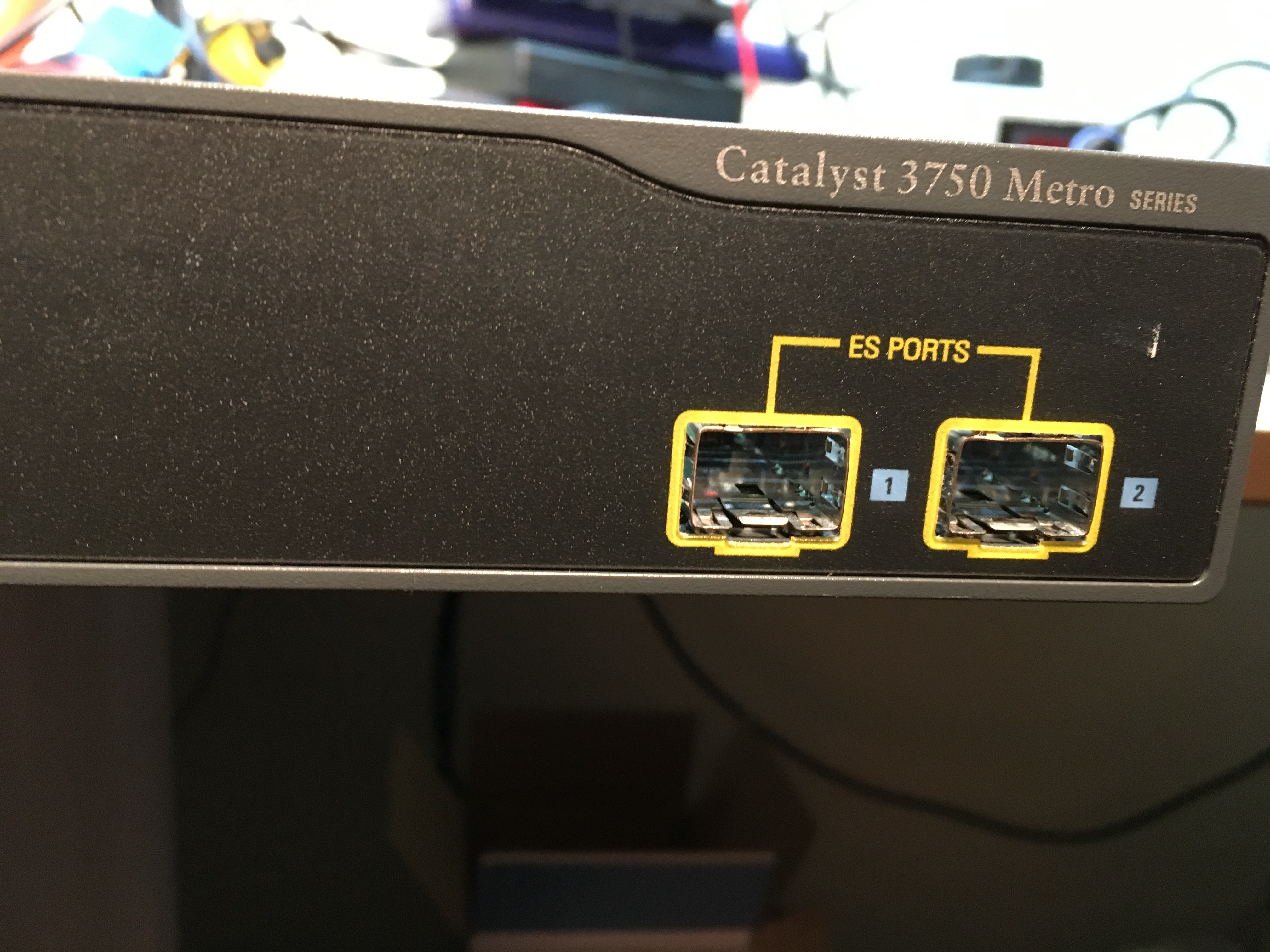
I for sure hate this, but in this case I thought: Well this looks like a power supply (PSU) failure. The switch in question is a Cisco 3750ME switch. And has swap-able PSU’s. So I swapped the PSU, but the switch won’t power on.
Time to take a closer look
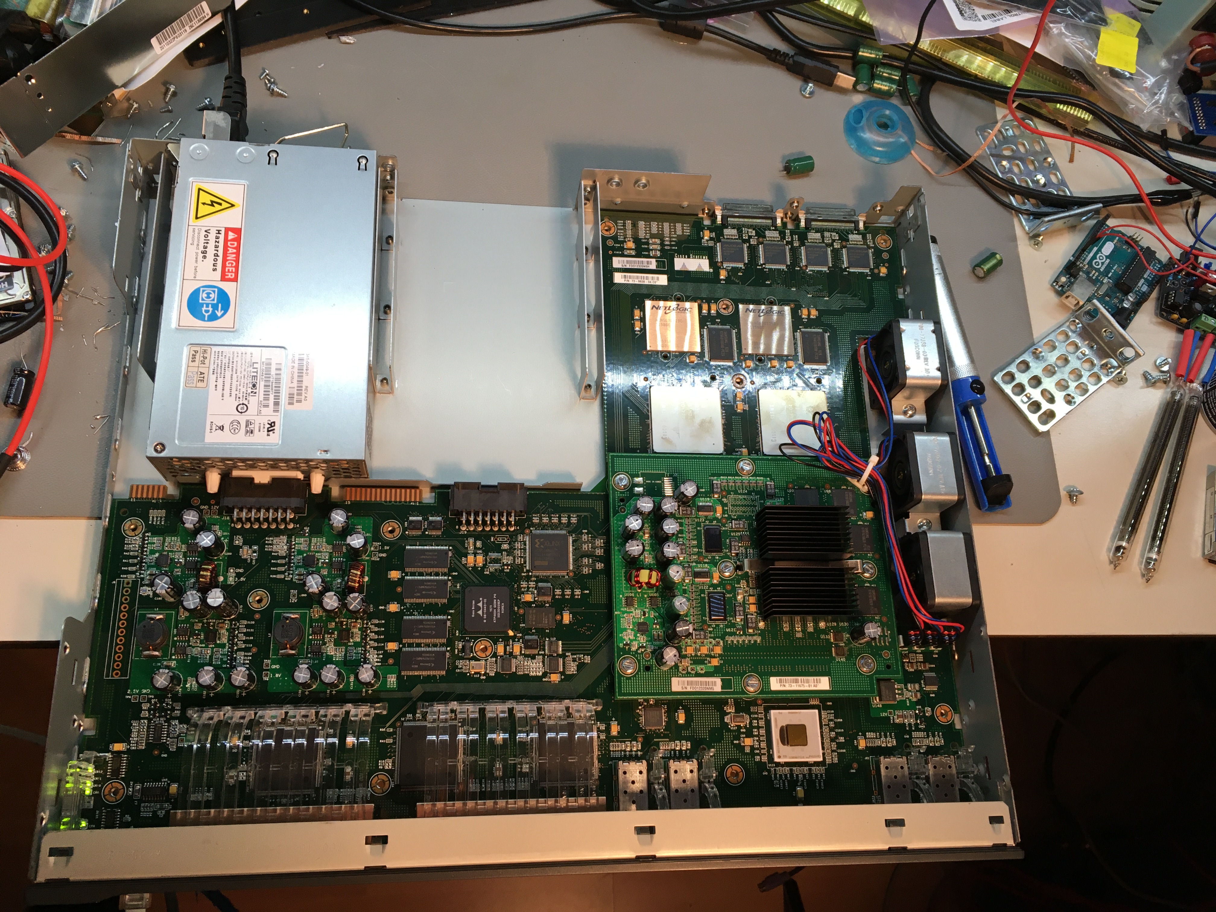 Since I figured out it’s not a PSU failure I started to take the switch apart. After removing the cover, I measured the voltage line. There is a test point on the main board which makes it easy to measure the 12V power rail. And I measured no voltage what-so-ever.
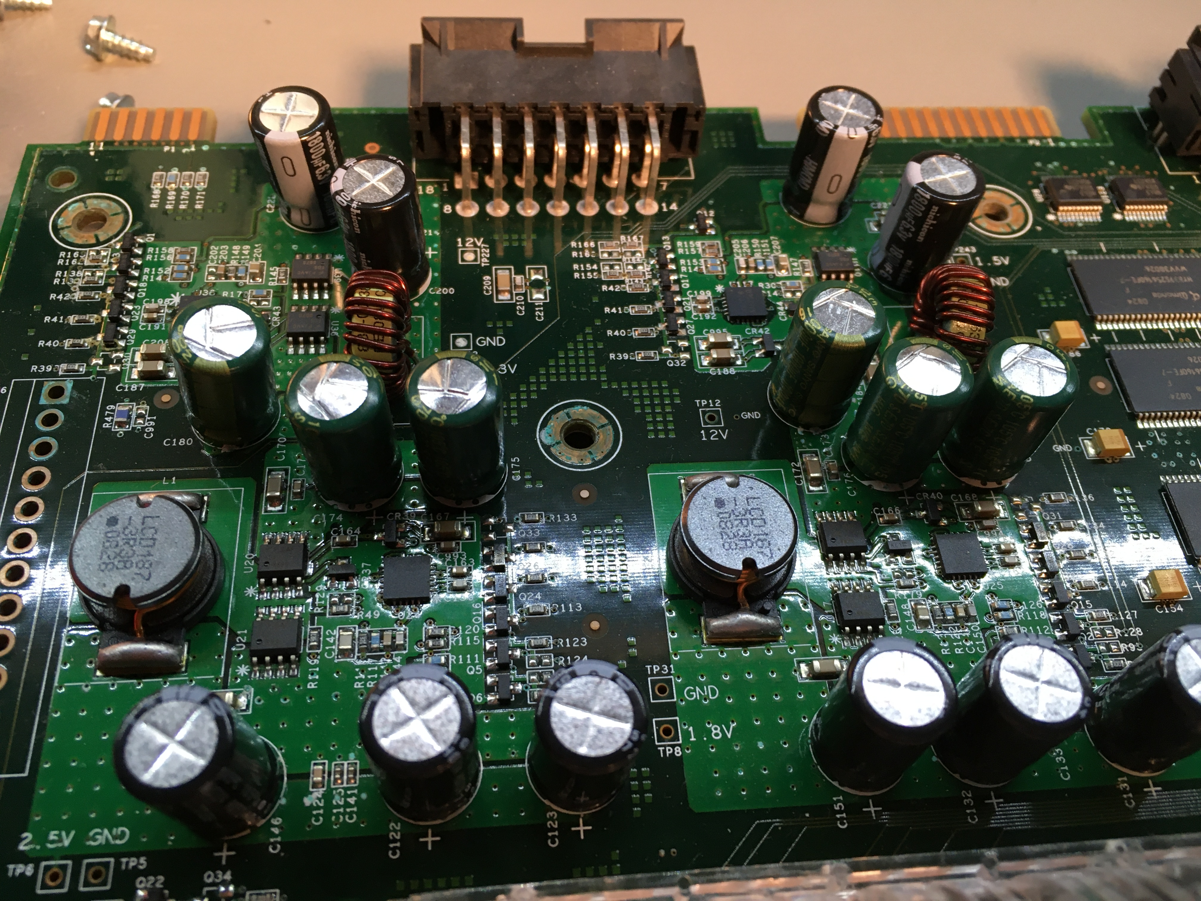
So I unplugged the switch from the mains, and measured a short between the ground and the +12v. Which didn’t surprise me at all. After opening the switch, I noticed a few capacitors which bulged.
Repair time
 So I started to take the switch completely to bits, since the main board has to come out. Their are a lot of screws. And taking the main board out is not that easy. But once the main board came out, I could start de-solder the capacitors which were bad. And this was a time consuming job. The mainboard is a multilayer board, with large copper plains, and getting the capacitors out was a real hassle.
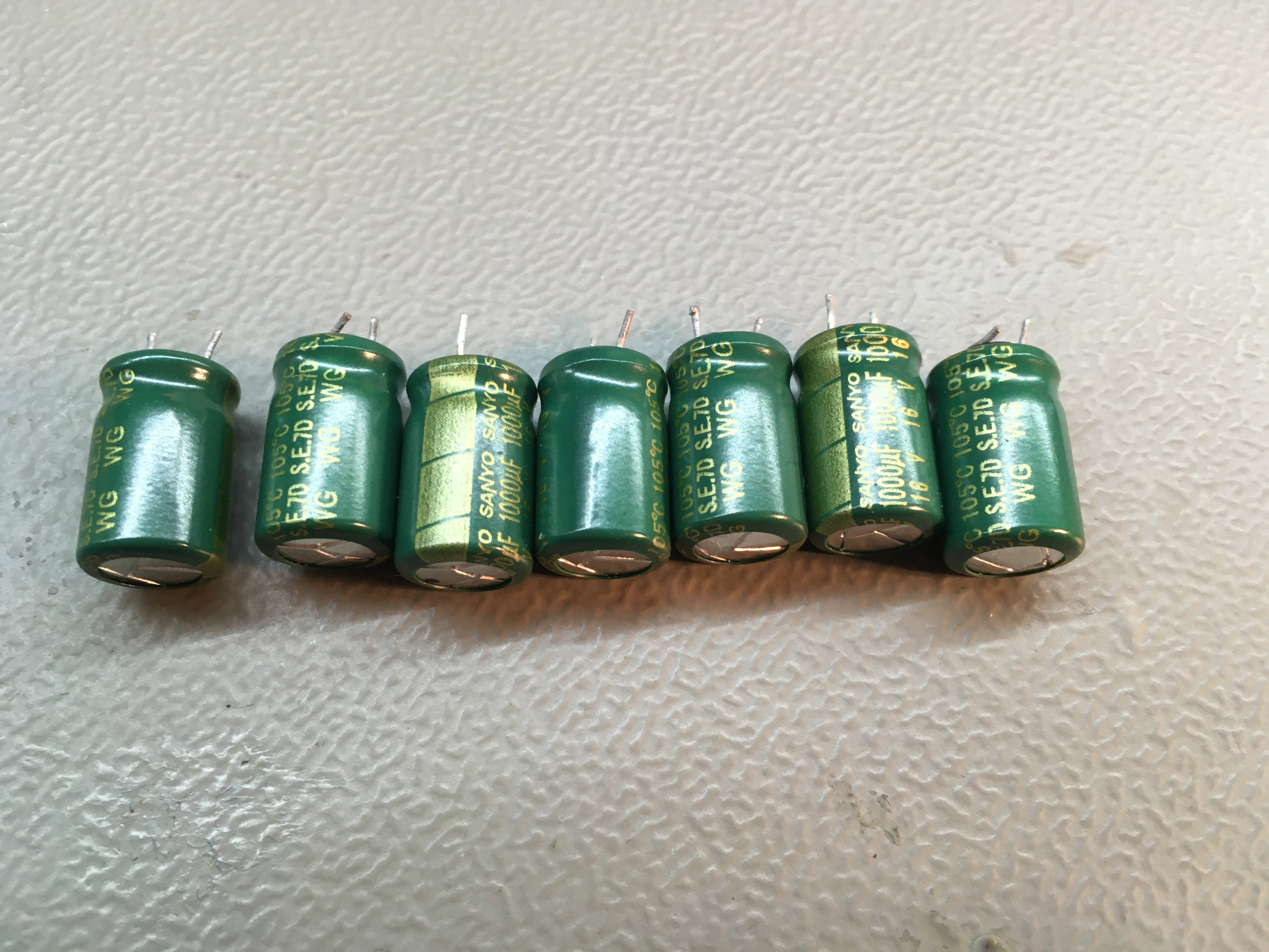
All the capacitors which had gone bad, were of the same type and values:
16V 1000uF
Taking them out was a real pain in the b*tt, soldering the new ones in, was not easy. After spending a couple of hours I manged the solder every cap back in.
A few tips on (de)soldering components on multi-layer PCB
 Soldering or de-soldering parts on a multi-layer PCB can be tricky, and difficult to do. First of all: take your time. Be patient, and don’t try to damage the PCB. So don’t use sharp screwdrivers on the PCB while trying to pry components of the board. If you damage a track or tracks, it can be hard or impossible to repair.
Use a soldering iron with enough watts. Multi-layer PCB’s can have large ground planes. And these ground plains can take a lot of heat. If you don’t have a soldering iron with enough power, you can (if you have one) use a hot air gun to preheat the board. Don’t set your hot air gun to hot. You don’t want to de-solder any other tiny components.
In this case, the capacitors where through hole components. And with these components one tricks works very well: Heat up one leg of the component. Wiggle or pull the component from the board with your fingers. Make sure you don’t burn yourself in the process. Let this leg cool down, and start heating the other leg. Apply pressure to the component again, lifting it from the board. Then let this leg cool down, and start heating the other leg again. And by heating each leg, gong back and forth and gentle forcing the component from the PCB.
Once the component is removed, the holes can still hold a small portion of tin, making it impossible to insert a new component. Getting the tin out of the holes can be a tedious process as well. First thing to try is to use a lot of flux, and fresh tin. Just fill the holes with fresh tin, and try to suck the tin out with a de-solder pump. You can also to try to use solder wick.
Don’t try to heat up the hole to long. You may damage the hole itself, or the PCB tracks around it. And that can be the end of the game. If you can’t get the tin out, the next may work as well:
Get a small needle and a pliers. Grap the needle with the pliers, and place the sharp point of the needle into the hole. Heat the hole and the needle with the soldering iron, and gentle (don’t apply to much pressure) puss the needle through the hole. Once all the tin is melted, wiggle the needle around, and pull it back up again. This way you may get enough tin out, the place the new component.
Finally result
 Once I soldered all the capacitors back in I started to reassemble the switch. Putting the main board back into the chassis, was not easy. After some tries I figured out it’s best to remove the light pipes, insert the main board, and place the light pipes on the main board once the main board is in place.
And as soon the board was completely assembled, I connected the switch to the mains, and it powered up with out a problem. Next I ran some diagnostics on the switch and it looked fine again. Last step was to place the cover back on again, and placing the switch back into the rack.