Connecting a Rohde Schwarz AMIQ to a SMIQ04
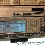
The first article explains how to setup an R&S AMIQ and talk to it, and to get signals out of the I and Q outputs. In this article the AMIQ is connected to a SMIQ04. In this setup the AMIQ provides the IQ modulation, and the SMIQ is providing modulated signal on its RF output.
Prerequisites
To be able to use the SMIQ and AMIQ together, a vector modulator (IQMOD variant 4 or higher (var. 8) must be installed in the SMIQ.
Connecting the R&S AMIQ to R&S SMIQ
There are a couple of options on how to connect and control the R&S AMIQ. It’s possible to control the AMIQ from the SMIQ. Or control the AMIQ by a PC.In this setup I’m connecting the R&S SMIQ and R&S AMIQ together by the use of an IEEE-488 cable, so GPIB can be used to control the instruments.
One think to keep in mind is that when using the SMIQ to control the AMIQ, the SMIQ is acting as a controller. And there can only be one controller active on the bus at the same time.
The output “I” and”Q” of the R&S AMIQ must be connected to the “I” and “Q” inputs on tthe R&S SMIQ.
Generating signals
When using the SMIQ as a controller, the signals of the AMIQ can be used as follows:
In the menu Utilities/Install the option AMIQ control must be enabled. After enabling the SMIQ must be rebooted.
After reboot an extra menu option: IMQ CTRL is visible. In this menu the following options must be selected and set:
-
- Start by setting carrier frequncy
- Set the level of the output signal (for example 0 dBm)
- Select the option: SELECT WAVEFORM
- Next select: Drive and choose C:
- Pick a waveform, or change to directory to select a waveform
- Press return and select menu Mode.
- In the Mode menu select AUTO
- Press Return key, and select menu option Level
- In the Level menu set the I and Q outputs to 0.5V/50 Ohm
- Press return key, and go to Vector mod, and set state to “On”
The modulated signal should now be present on the RF output.
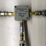
 To demonstrate a modulated signal which is generated by the AMIQ I use a directional coupler.
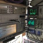
 I connected the directional couple’s input port the the RF output port of the SMIQ. The output port of the directional coupler is connected to a Tektronix 2225 scope. The CPL port is connected to a HP8591A.
Note that I connected the NOT I port, so I could create a interesting signal, which is a challenge to trigger on the Tek 2225.