Introduction
In part one we looked at the history of repairing a Tektronix 2225. At the end of part 1 the Tektronix 2225 scope is in a working order, but it has a lot of cosmetic issues and other issues. To summarize:
-
- The plastic back cover/panel is heavily broken
- The front panel is a France panel, and it is heavily broken
- Lot of knobs are broken / damaged. And some are missing.
- The case cover is in a bad shape
- During the process of straighten the chassis one of the bolts pressed into the chassis broke of
- Fuse holder is missing.
So to get the scope into a working and decent state requires some fair amount work, but obviously a lot of spare parts. The problem with spare parts for Tektronix scopes is: They are not cheap. So I started to look out on a complete none working Tektronix scope, which I could score cheaply.
And this took some seriously searching. Most of the scopes which are not functioning have also severe cosmetic problems as well. Most of the front panels have damage on them, back panels are missing, knobs are missing etc. And sometimes the phpto’s provided are not clearly showing the amount of damage. So it’s a gamble to buy one.
But one day I found a Tektronix scope which was more or less in a good shape. I could see the front panel had taken some hit, and could be damaged, but it could be alright either. It was hard to tell from the picture. It has some knobs missing, but with the knobs I already had I figured I could restore the scope. The listing mentioned:
This Tektronix 2225 Oscilloscope 50-MHz looks to be in good cosmetic conditions with signs of wear and previous use. (missing/damaged knobs)

Unit powers up; however, I lack the knowledge and equipment to test properly so it is being sold as-is.

Unpacked dims 19*16*7. See pictures for more details.

Please ask questions or indicate concerns prior to bidding. By placing a bid, you agree to all stated terms. All auctions are sold as advertised, as is and without warranty, unless otherwise stated in the item description.
No software, power cords, or other accessories are included unless stated above. See additional terms of the auction below.
I figured I could take a gamble if I where to get 50% or so off.
Since this scope costs 200 dollar (which is about 172,40 euro's)
shipping is 88,50 dollar (which is about 76,28 euro's)
total of 288,50 dollar (which is about 248,68 euro's).
And then I have to take into account the customs and import taxes / BTW costs.
So I did make a offer of 100 dollar (86,20 euro’s ), and to my surprise it was accepted. So I ended up paying:
scope costs 100 dollar (which is about 86,21 euro's)
shipping is 88,50 dollar (which is about 76,28 euro's)
total of 188,50 dollar (which is about 162,51 euro's)

Which saved me : 248,68 - 162,51 = 86,17 euro's.
The disadvantage of buying overseas are the customs costs. In this case I had to pay an extra 47,08 euro’s, which brings the total to 162,51 + 47,08 = 209,59 euro’s.
But.. If I had to collect, haunt down all the parts I needed, it will cost me properly a lot more.
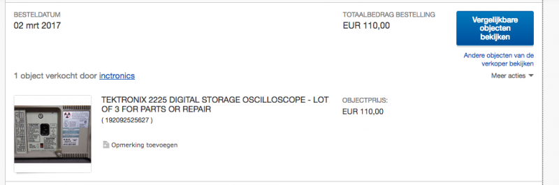
So in the end I payed 110,00 euro’s for 3 scopes right ? So that is 1110 / 3 = 36 euro’s per scope. So to get this scope neat and decent again, it wil cost me : 209,59 + 36 = 245,59 euro’s. Considering that good working Tektronix scopes go for about 300,00 / 400 euro’s this is not a bad deal.
But sometimes this is not about the money you put in. It could be a labour of love, the passion about these equipment. And not to forget the knowledge gained when learning along the way.
The donor scope
Once the donor scope arrived and I tested it by powering on, and the scope works well. The scope is way out of specs.. but functioning. So I had one dilemma, should I used this scope, and calibrate it, or going ahead as planned, and restore the scope I wanted to restore in the first place ?
I decided to stick to the plan, and restore my own scope. And this turned out to be quite some work.
So what gear is needed to get this scope in a good shape ?
-
- Torx bit set
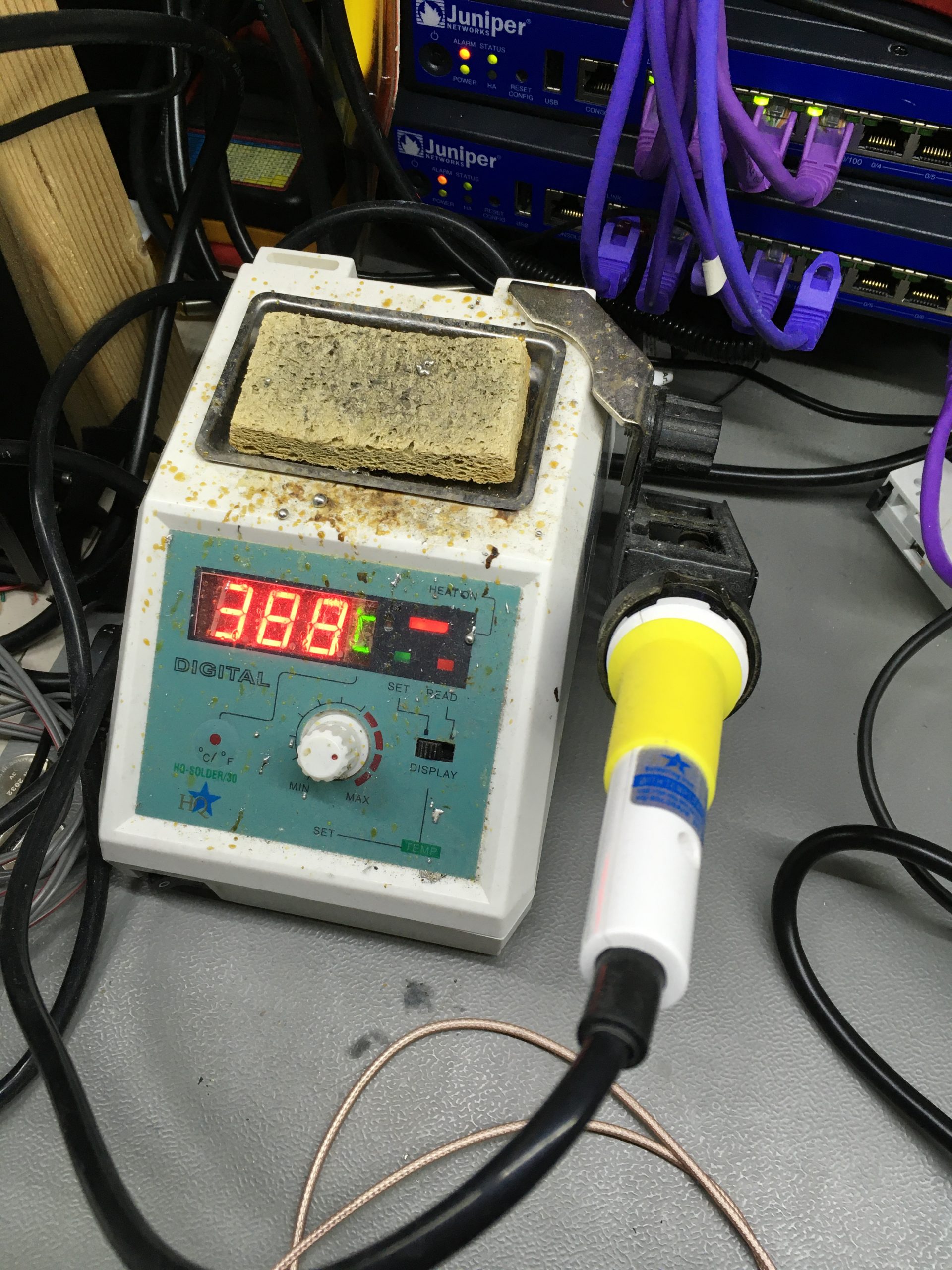
- Soldering iron
- Pliers
- Plastic bags
- Pieces of paper
- Camera (for taking photo’s, you can use the camera of your smartphone for instance)
- And a lot of patience 🙂
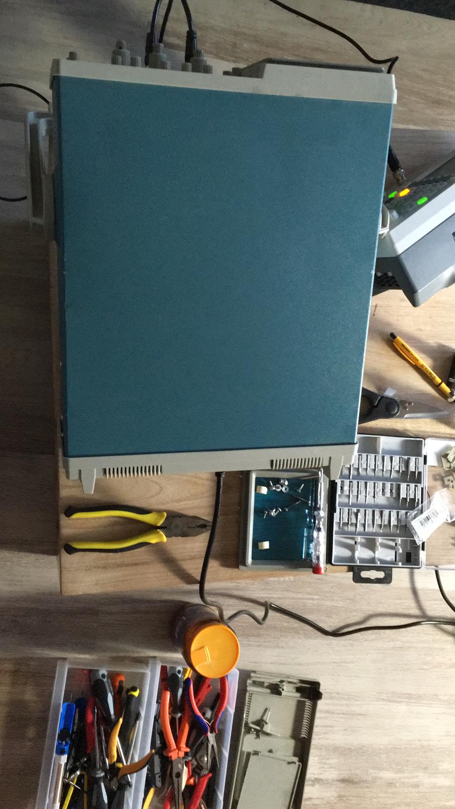
Starting the restoration
The Tektronix 2225 has a lot of different screws, so every time when a part of a scope is taken apart, create a label, and describes where the screws / washers/ nuts / bolts / small part is coming from. But the label and parts in a plastic bag.
And before taking the scope apart make photographs, so it’s easier to put things together. Basically documenting every step in the tear down process.
Another tip is: start with taking apart one scope, and use the other scope as reference. In this case, since the various stages of repairing the scope which is going to be restored has lot of parts (screws etc) missing. Luckily I have another scope I could as reference, and I took a lot of pictures. And since I messed around with these scopes a lot, I can almost take them blindly apart, and put them back together again.
Another thing you have to take into account is safety. These scopes have high voltages inside of them. So be very aware of that. If you take precautions you should be safe. However: If you do not feel comfortable dealing with high voltages and CRT screens, then don’t mess with these devices.
I don’t feel comfortable messing around with high voltage stuff, so I always discharge CRT’s and capacitors. Since I don’t like to be zapped by them. And these capacitors can hold a lethal charge! Or they can hurt you really, really bad.
So: Always discharge the CRT and the capacitors in the power supply!
I noticed that letting a Tektronix 2225 overnight without the mains power cord plugged in, takes away most of the charge. Making discharge process a lot easier and safer. But whatever you do, don’t assume the capacitors are discharged in anyway! Safety first.
At this point It maybe sound like a very complicated thing to do, by taking two scopes apart, and “merge” the two scopes into one working scope again. But since all the troubleshooting is already done, and effort has been made to make sure that the donor scope is in a good working order.. It boils down to: unbolt things, and bolt them on again.
The important step is: document everything you do. This may sound like an extra step, which is going to take extra lot of time. But that isn’t the case. Figuring out how things must be put together while going through a pile of different screws and parts will take you much longer (if you ever can sort it out). So the whole idea is: prevent this from being a giant 3D puzzle. And you should be okay.
From experience I can tell that taking two Tektronix 2225 scopes apart, and building one scope again take a long day. So just take your time. Be patient keep your calm, and just go on. Since this is a hobby project, there is no deadline. During the restoration process my living room (which I try to keep clean from parts and broken equipment) turned into a workshop kind of place for almost a week. Scope parts where all over the place.
But this didn’t bother me, since I know it would be for a small period of time. And once I got my scope back into shape again, I could just bolt the donor scope somewhat together. I doesn’t have to work right ? I just bolt it together so I don’t loose part, and don’t damage the CRT (for instance).
Taking off the front panel
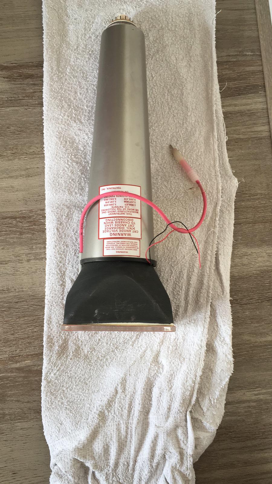
The first step is to dismantle the donor scope, by taking off the front panel. But first step is to discharge the CRT. Before the front panel is removed, the CRT must be removed from the chassis. When removing a CRT, do this very gentle. You don’t want to beak the CRT. Since a CRT is vacuum tube, it can implode, and then explode. So be very careful.

Before the CRT can be removed unsolder the wires which controls the rotation of the CRT. (The wires goes to a spool, forming a electromagnet.) Take not of the wires, as they are polarized.
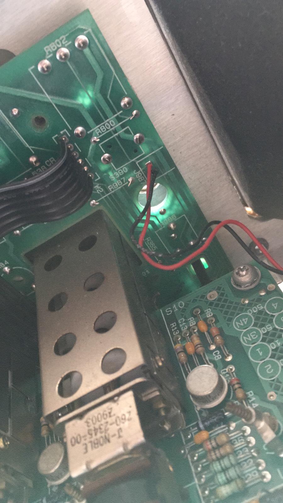
When the wires are no longer connected to the main board, the CRT can be softly and gentled pushed forward, out of the chassis. The CRT is hold by pins at the back. So do this carefully. You probably want to wear safety goggles when doing this. If for some reason the CRT implodes, your eyes are protected. Better safe , then to be sorry) Store the CRT on a soft surface, or lay it flat. Make sure that you don’t damage the CRT (this can be expensive).
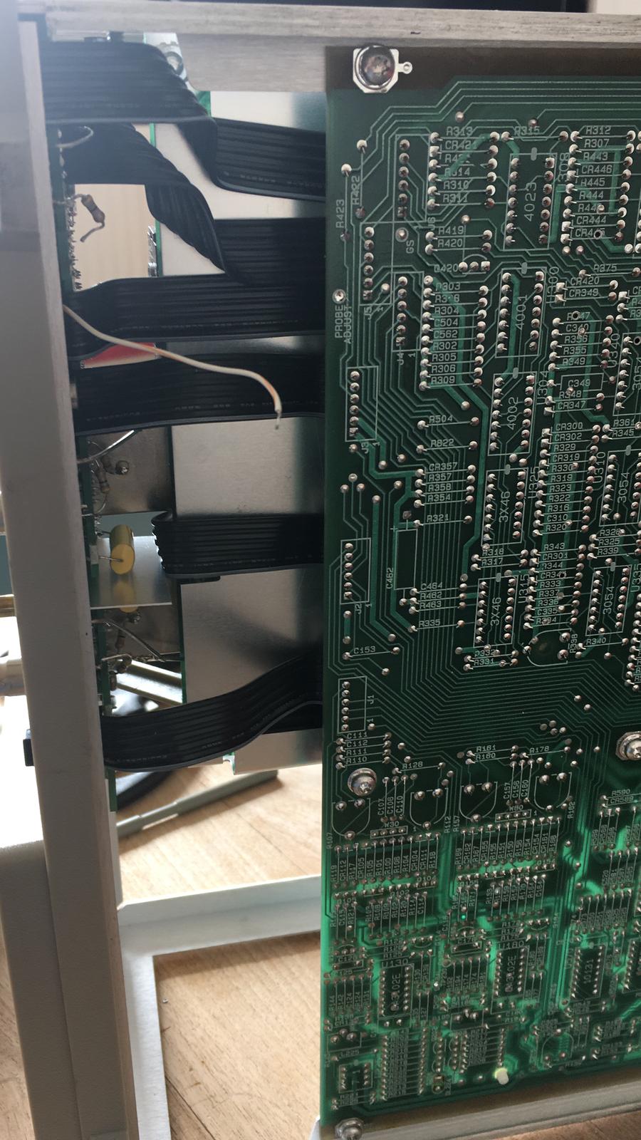
Once the CRT is out of the way, a couple of things needs to be disconnected from the front panel, by de-soldering: These are the Ground leads of the BNC, and the 47 Ohms resistors from the BNC’s. Also unsolder the wire which is for the compensation of the probes.
When all the wires are disconnected, the next step is to unscrew all the nuts of the front panel, and take off every knob. Be careful when removing the knobs. The can easily break off, since the ageing of plastic.
The next and last step before the front panel can be removed, is to remove every screw holding the front panel chassis part in place. So unscrew the screws from the main board, and from the chassis.
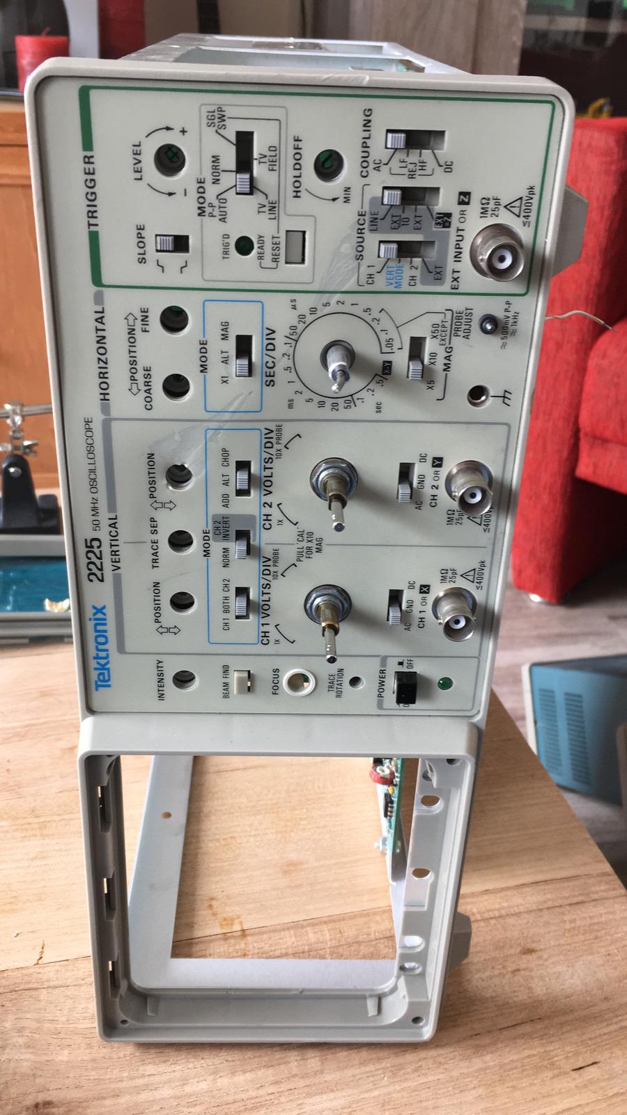
Once the front panel is removed, it can be put aside. The same procedure for removing the front panel must be done for the other scope as well. Only this time, make sure to remove the front panel very gently. So that the plastic switch gliders stay in place. Once the old front panel is removed it can be places back. This can be a fiddly job. Just take your time, and gentle place the front panel in place, without forcing it. Once the front is back into place, it looks like this:

Replace the bent part of the chassis
After the front panel is replaced I replaced the bent part of the chassis. Since I got the parts, this is a wise thing to do. The frame will be straight again. But in this case, one of the pressed in bolts are gone, so attaching the back panel isn’t going to work.
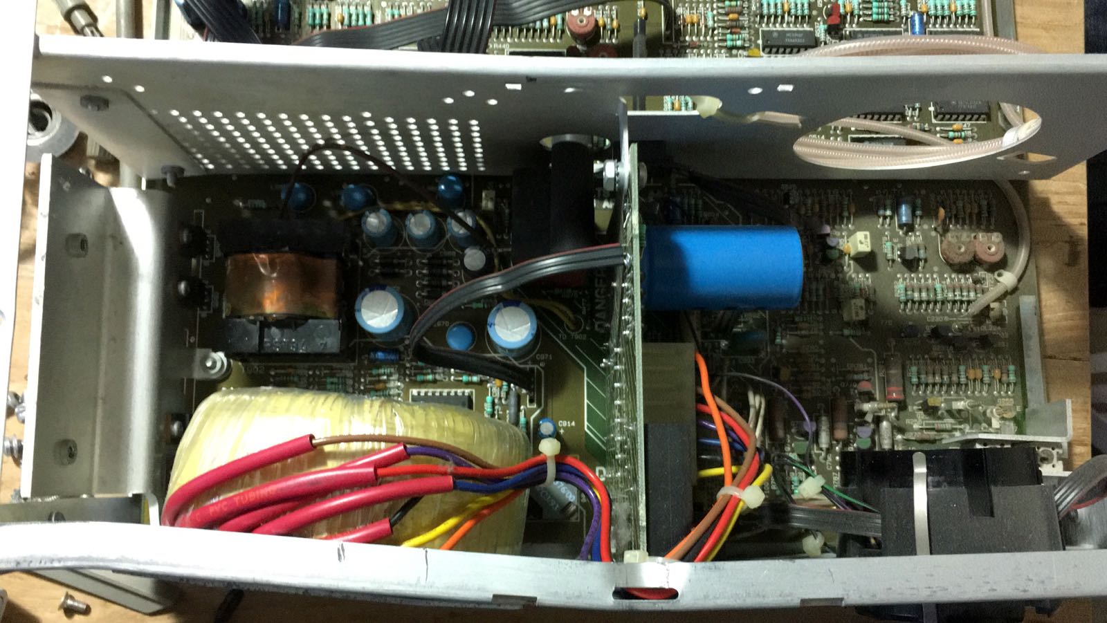
To remove this part of the chassis, the CRT socket must be removed from the back. This is easy to do, by removing the metal clip. Then rotate the socket, so that it can pushed inwards the scope. Unplug the Transformer connector. I decided to leave this one in place, and didn’t unbolt it from the chassis. Next unscrew every screw from the main-board, the chassis and part of the attenuation board.

Replacing this part of the chassis is relatively easy. Just place the chassis part in place, and bold on the main board, and to the reaming chassis. Reconnect the Transformer (make sure to plug in the connector at the right orientation). Re-seat the CRT connector. And place the metal clip back.
The last steps
At this point, all the knobs can be placed at the front panel. And make sure that every bold / nut is screwed on tightly, since they are attached to Ground. At this point the scope should look complete again. The steps to complete the rebuild:
-
- Reconnect the probes compensation wire to the main board
- Reconnect every ground wire onto the BNC’s again
- Reconnect every 47 Ohms resistor
- Reconnect the CRT anode
The end result
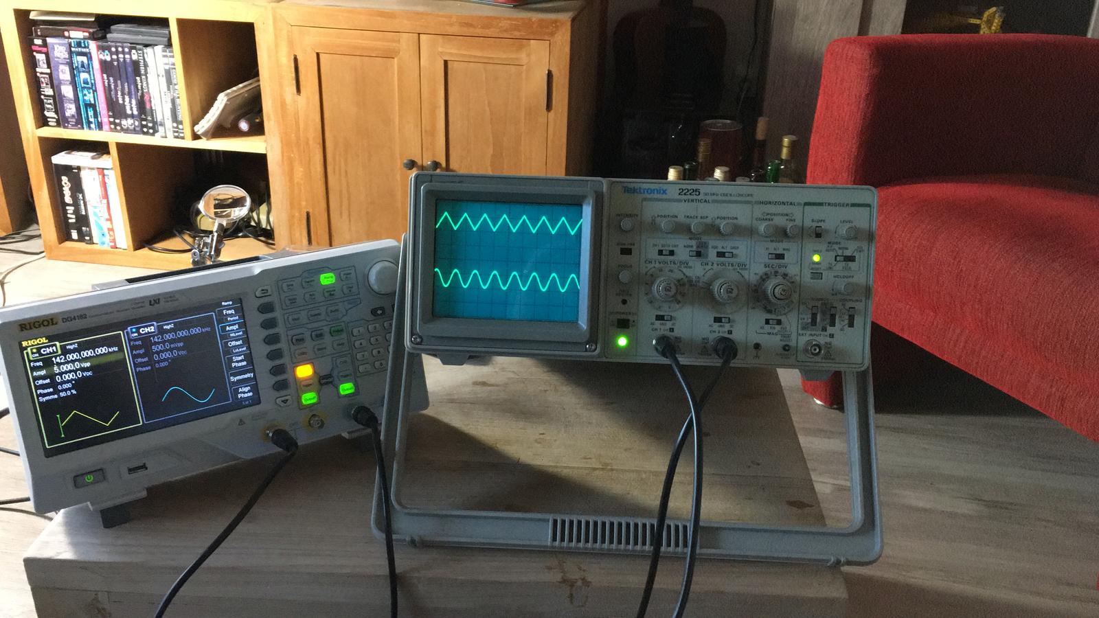
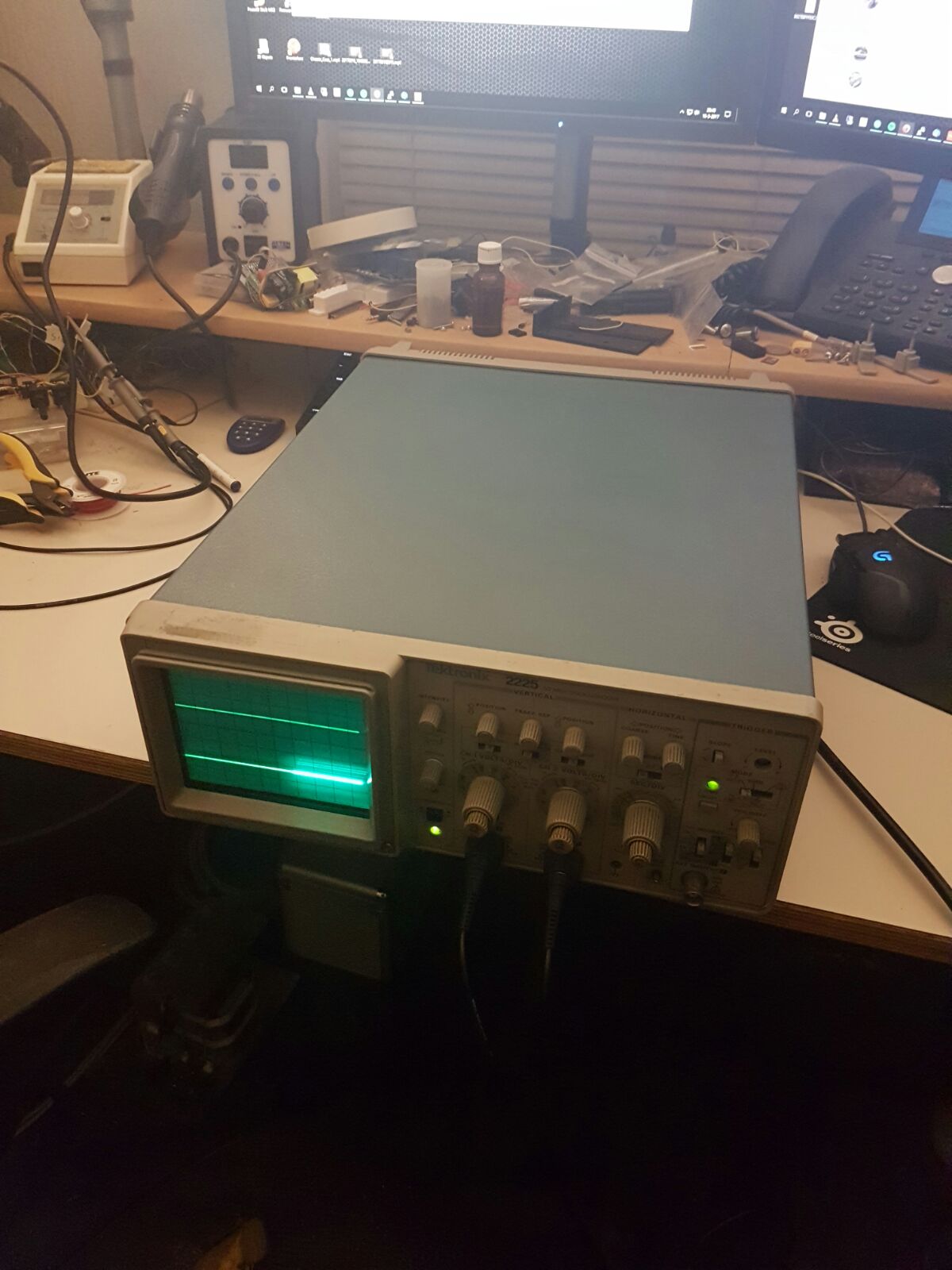
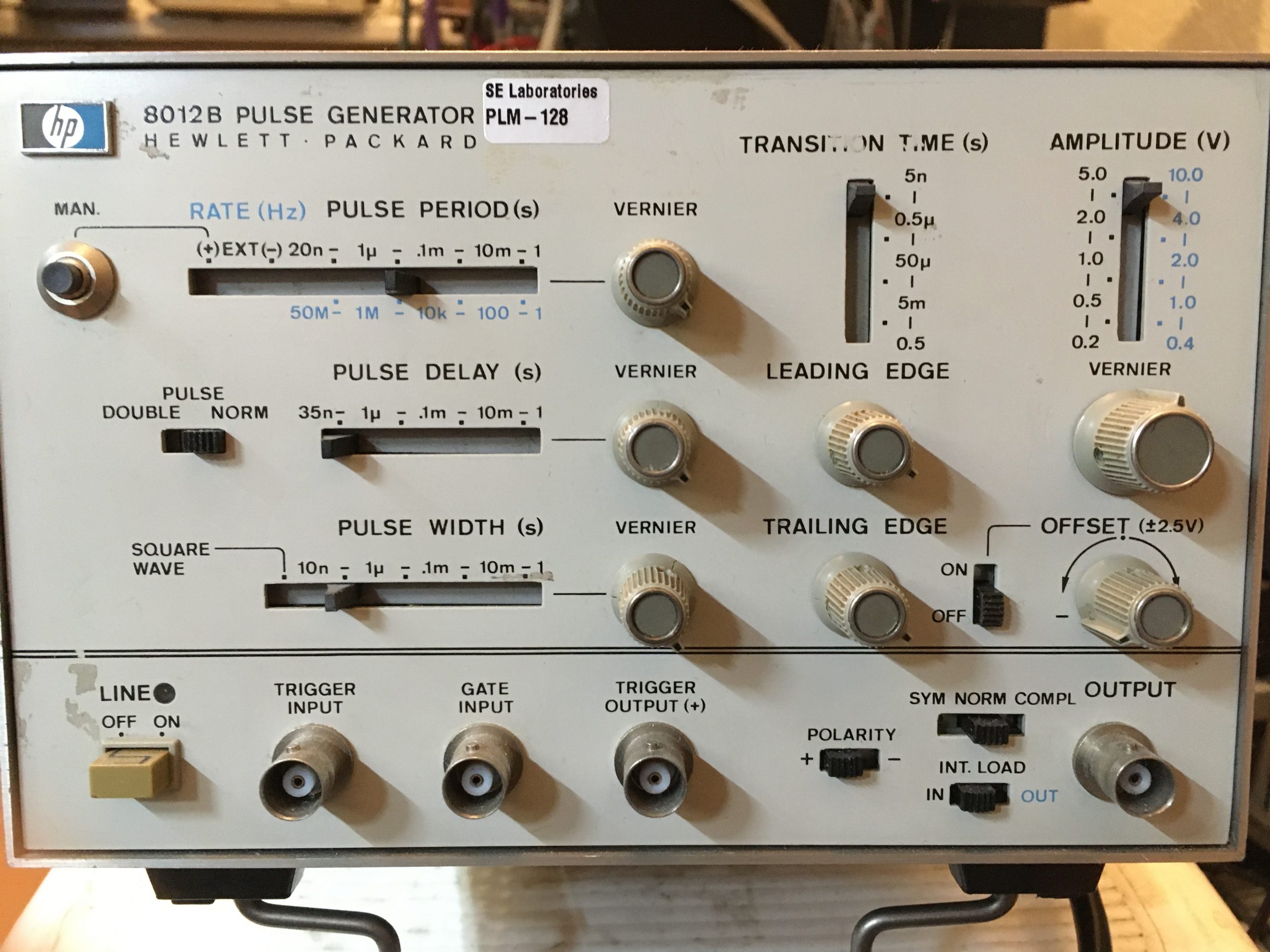
Once that is done, the scope can be tested, by putting a signal onto it. Once confirmed working, attach the cover, and this should be the end result.
At the end it’s nice to compare how the scope looked like, and looks after the complete restoration:
The original France front panel looked like this:

And now looks like this:
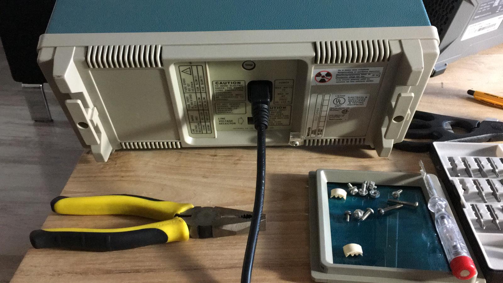
And the original back of the scope changed from:
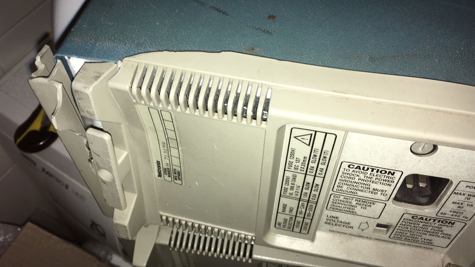
Which now looks like:
The cover looked like this:
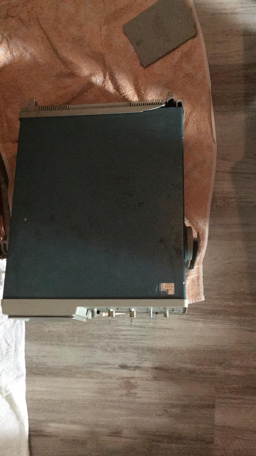
And now looks like:
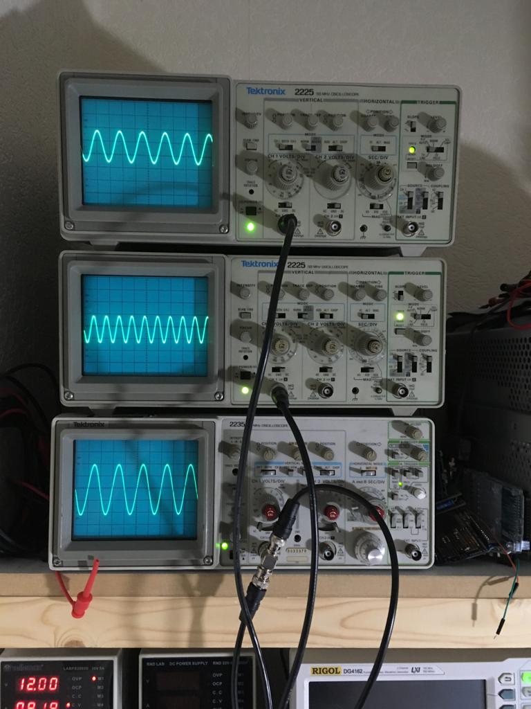
All in all I’m very pleased with end results of this restoration / rebuild of the Tektronix 2225 scope. It’s amazing that at the end all the three scopes are working again. It took same fair amount of time and dedication. But again, I’m very pleased with the end results. And along the way, Dave and I had a great time working on these scopes. And I’m very thankful he helped me through the whole process.
And last but not least, all my Tektronix scopes are now in a working order, and this really puts a smile on my face. Because face it.. nerds going to be nerds. Below the two 2225 are working. The scope on the bottom is a Tektronix 2235


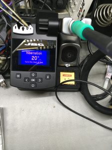 I looked around for a good replacement, taking the requirements into account. And finally came to the conclusion it’s better invest more money, then trying to save some money and go for a cheaper solution, by looking into clones. So I bite the bullet, and decided to go for a JBC station. These stations are not cheap, but in every test I have seen, the JBC just leaves all the others behind in terms of performance. Furthermore I looked for example at Hakko stations, but the don’t have a small footprint. Well they have a large order of different tips, the JBC even has more choice. Also the operation experience is better on the JBC.
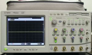
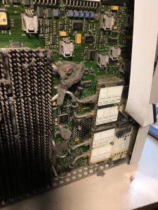 So maybe the card has bad contacts, so I decided to remove the case, and take a look inside. And that is when I noticed a lot of dirt. I have seen dirt in machines, but this is really bad. I cleaned most of it. Cleaned the A6 board, and sprayed some Deoxit on the contacts. and reinstalled the board. Unfortunately, the problem stayed.
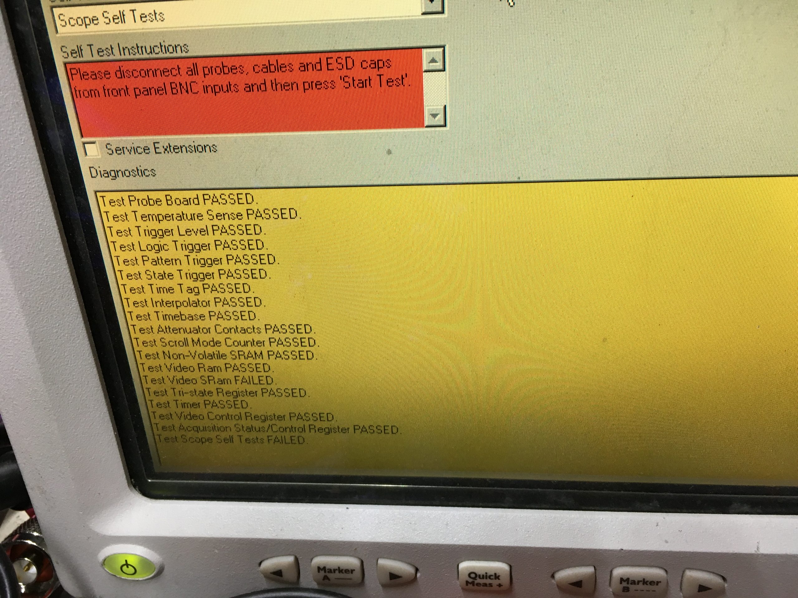
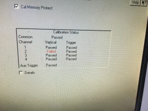 I went ahead and tried to calibrate the scope by using the self calibration process. This is a straight forward process. It only takes some time to complete.