Repairing a Tektronix PB200 Bert tester

Before diving into repairing the Tektronix PB200 BERT tester, let me explain briefly what a BERT Tester is. BERT stands for ” bit error rate test ” In the most simple form, a BERT tester sends out a random bit patron, and an analyzer receives the bit pattern and compares this bit pattern to see if there is any bit error.
Obviously this is more complicated, how does the analyzer now what the original bit stream was ? The theory behind it this is quite complex, and beyond the scope of this article. For a more in depth explanation see [this] Wikipedia article.
A device like the Tektronix PB200 is used to test different data transmission devices, like optical interfaces, or a like.
The Tektronix PB200 has a data generator and an analyzer built into one device. The specs for this device:
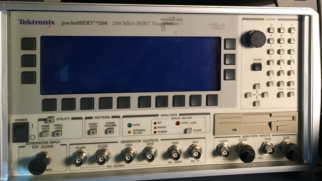
A Tektronix PB200 which is dead
Before I can play around with this PB200, the device needs a repair. I bought this device as a “none working, for parts”. And well.. it sure is in a “none working” condition, since the device doesn’t power on, at all.
That is one of the reasons I bought this device. When a device is not able to power on, this normally means the Power Supply (PSU) has a problem. The downside of this is of course that their is no easy way to test the rest of the functionality of the device.
Assessment of the problem
Once the devices arrived at my doorstep, I could inspect it further. And I noticed a sharp bent in the front panel once I removed the covers. Not a good sign to start with. The second thing I ran into is that this device is a complete nightmare to take apart. The construction is just horrible. Screws on places which are heard to reach. I suspect this is just a branded by Tektronix. I got my hands on some Tektronix equipment, and repaired some, and the construction is always good engineered. In this case, it’s definitely not.
So it took a lot of effort to get the PSU out of the chassis. Once the PSU was out I noticed a burned up diode, and a burned spot on the PCB. A quick check of the fuse confirmed: This PSU had a very bad moment. This means that on the primary side of the PSU a lot of other components could be damaged. So the first thing I did was to hunt for a Service Manual, and well these cannot be found.
So I started to de-solder the diode, so I could get a marking of the component. The diode was next to some transistors, or MOSFETs so I decided to desolder them as well, since they are most likely also damaged , or are the cause of the damage.
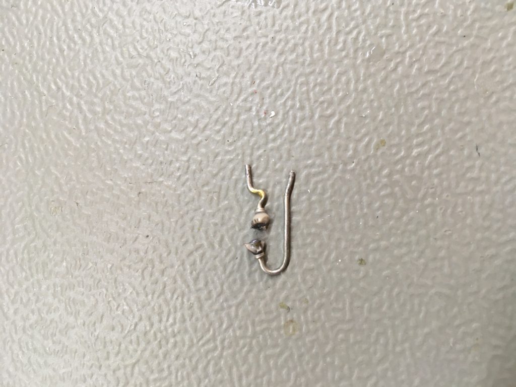
While taking the diode out carefully, I could not prevent it from falling apart. 
The diode literally exploded and split into halve. With a lot of trouble I managed to get some marking, but I wanted to make sure that I got it right. Primary side of a PSU always makes me nervous. So I started a [thread] on the EEVblog forum.
Another member also suggested to get a PSU replacement, which is almost the same. The only difference is the output voltage.
So I decided to buy this PSU, so I have a reference, and if I’m unable to repair the primary side of the PSU I could perhaps convert the secondary side so it gives the right voltages.
In part [two] I’m trying to fix the PSU