Introduction

This article was on my internal wiki, and finally came around to publish it. Once you started with electronics and learning, their may come a point in time you want to actually repair stuff. In my case this point in time came when I stumbled across a Ebay listing on 18 feb. 2017 which listed the following: “TEKTRONIX 2225 DIGITAL STORAGE OSCILLOSCOPE – LOT OF 3 FOR PARTS OR REPAIR” I started to mail the seller and asked a couple of question, like: do they power on, and “is the CRT working”.
I got a reply , but none of my questions where answered. The answer was:
“It is 3 ossilloscope sold in the state for parts Ideal for do-it-yourself-er. Attention heavy products.”
So the lot of 3 none working scopes where 150,00 euro’s. Since I didn’t know anything about their state (except “for parts”.) I decided to get the scopes for 75 euro’s where I wanted to pay a max of 120 euro’s. I finally negotiated a deal for 110,00 euro’s for 3 none working scopes. And so on 2 march 2017 I purchased the scope.
This for sure was a risk. I didn’t know anything about repairing scopes. Hell I even didn’t know if I would be able to repair the scopes in the first place. But I figured: In the worst case scenario I ended up with a lot of parts I could sell, and make even a profit on that.
The main concern was the CRT part, and therefore the high voltage section. But I got one trick upon my sleeve. And that trick came in the form of a good friend of my called Dave Donker. He is very knowledgeable when it comes down on stuff like this. And I talked him more or less into this project. And the deal was quite simple: If he would helped me to get the scope fixed, and we managed to get two scopes out of three working, he could take one working scope with him.
Of course this is still a gamble, since the scopes had still to be received by me.
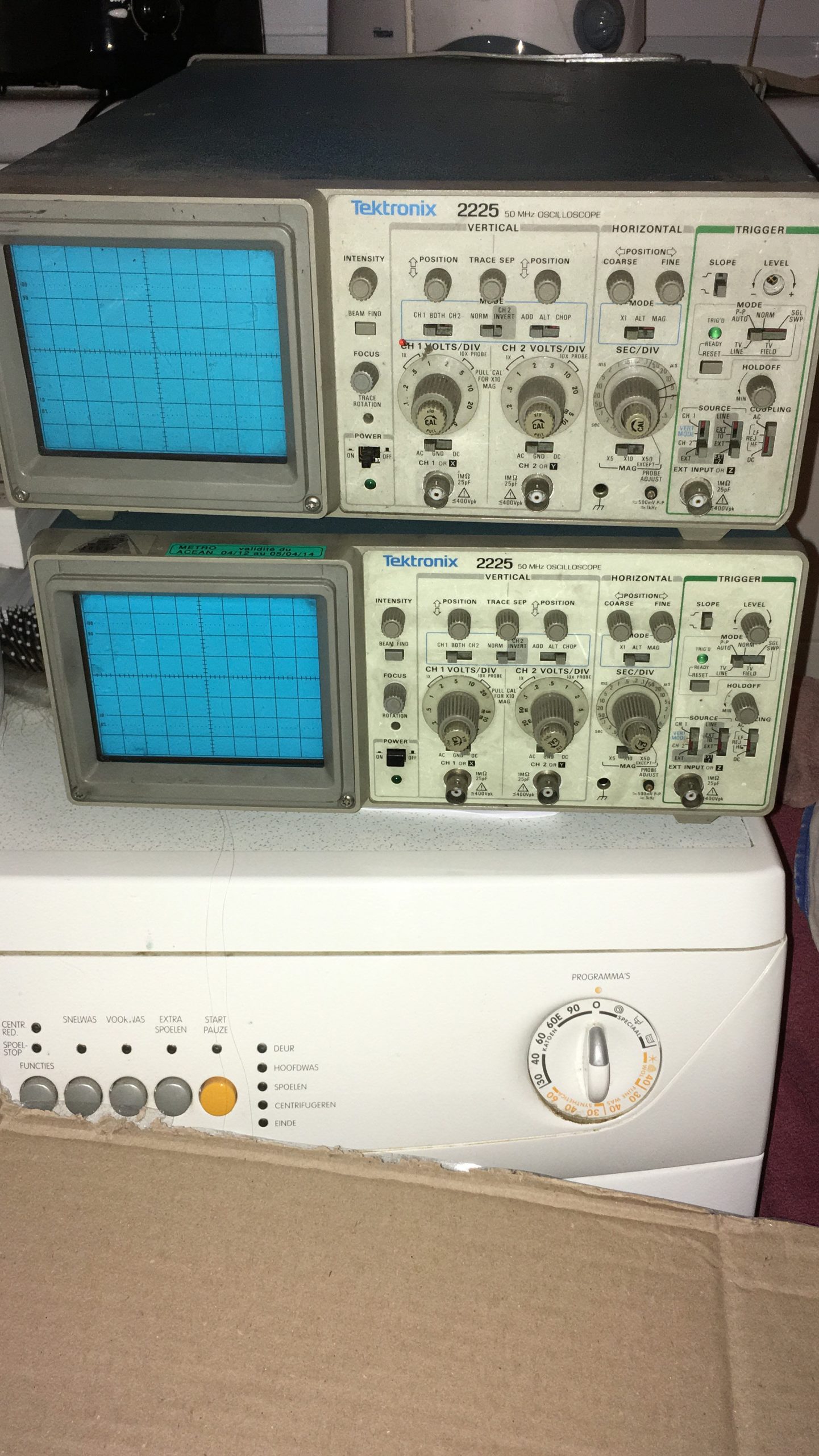
The scopes arrived in two batches. I can’t recall the exact date’s they arrived, but the first batch was of two scopes, and one separate scope. And the first impressions where “What have I done .. “. The scopes where really , really dirty. They where in a a really bad shape. And one scope looks like it was dropped of a 10 floor building.
If you look at the photo at the right and click on it for a larger picture, you can see what I mean.
The scopes are dirty, but that’s not a real problem. There are knobs missing which is of a greater concern. But if you look really close on the top one, you see that the cover on the back has a large dent in it. More on that later on.
The reason for picking up the 2225 is not without a reason. The Tektronix’s 2225 scope has a really nice feature, and that is it can be set to 0.5 mV/Div. So it is really suited for measuring volt rails of power supply’s and look at the ripple’s. Another reason is: they are relative easy none complicated scope, since these scopes are pure analogue scopes. So no “digital storages” scopes.
The specs of the scope are:
-
- The Tektronix 2225 is a 50 MHz dual-channel analogue scope.
- It has a single timebase with a magnifier that allows displaying normal and magnified traces together on the screen
- Has no delay feature, only an X position control.
- The Y inputs feature a x10 magnifier that decreases bandwidth to 5 MHz but increases sensitivity to 0.5 mV/Div.
The Tektronix 2225 was introduces in 1987.

The excessive damage on the back of one of the scopes. When you look at the damage on the back of the one of the scope’s you can see how much force it took to make a dent like this. So my first idea was: this scope is only for parts, and it is probably beyond repair.
Restoration day
 Detail look on the bent chassis.
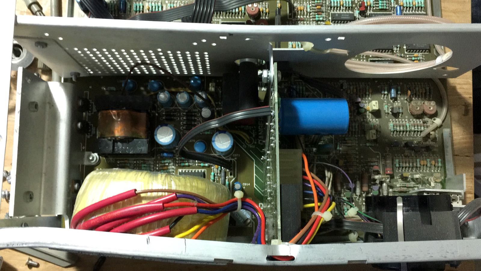
As agreed One day Dave showed up, and we started to look at the scopes, and assess what we do with the three scopes. Most of the scopes made some rattling noises when you shake them about. So we had to open them up, to take a look inside. And by none of the scope we could see any crucial parts where broken of. Most rattling noises where from plastic mounting holes of the front plate, which where broken of. While the inside of the scopes where dirty, but looked intact.
We put aside the heavily damaged scope. And concentrated on the scope which looked somewhat alright. And one scope came alive without any problems. It just worked. So we put that one aside as well. The other one which looked alright had some problems. The trace wasn’t stable, and seems to disappear whenever it likes to do so, without any logical reason. So before trying to troubleshoot this problem we turned or attention to the heavily damaged scope.
A scope with serious damage
We noticed very soon that the damage to this scope must be quite severe, since the cover was really stuck, and we could not slice the chassis out of it. At closer inspection we noticed one of the points where the carry handle was attached to the cover has a dent as well. We tried with a hammer to get the cover off, we tried pulling it with both of us. One holding the cover, and one holding the chassis. But since the edges are sharp, and we didn’t want any injury we stopped that experiment.
Next we started with pliers, and screwdrivers to force the dent outside of the cover, and after several hours we managed to get the cover off, and we could take a closer look at the chassis. We expected that real heavy damaged near the power supply at the end of the main board, and that even the main power board would be cracked.
But to our surprise it look all in tact. We could see that on part of the chassis was bent inwards, so it would shorted out a part of the main board. So we didn’t dare to power it on and give it a try.
We turned our attention back to the other scope with has the disappearing traces. We figured we could perhaps replace parts. So we started to disassembling the scope. We soon discovered that it was a lot of work to take the scope apart. To remove the front panel we had to unsolder a lot of stuff , the BNC connectors are solder with a Ground wire and termination resistors to the main board.
Since it was already getting late, we decided that Dave took the two scopes with him, to create one working scope.
Two working scopes
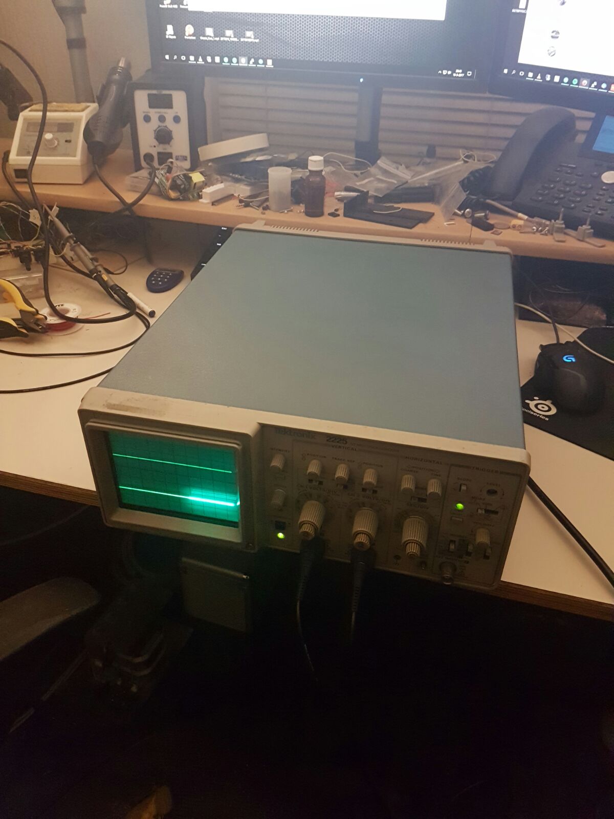
On 16 March 2017 Dave posted the picture you see on the left, showing a working scope. He had to put much work into getting the scope working. He straightened the chassis of the heavily damaged scope, so that the cover more or less could be fitted on the chassis again, and he also made sure the chassis was not shorting anything out on the main board. At that point he could test the scope by powering it on.
And to our surprise the scope worked without any problems. So he decided to take out the main board of this damaged scope, and place it onto the the scope with the straight frame, to get that scope working again.
At that point we decided that the heavily damaged scope was just for parts (as we already concluded earlier.) After swapping the main board, Dave had a working scope again. And so from the three scopes, we had now 2 working scopes.
We started discussing what to do with the last none working scope. We concluded that the original idea was: That I wanted to troubleshoot and repair some broken equipment. And well.. we sure got one at hand.
So long story short: One day Dave showed up at my house, bringing one scope back, which was more or less put together, but in a state where it was ready to be powered on, so I could started troubleshooting the thing. Dave told me at that point, he did some investigation and he found a pre-amp which wasn’t working, but also told me, he hadn’t have any clue what was wrong that part of the circuit.
In part two, I’m going to focus on getting the chassis more straight, and start troubleshooting.