Introduction
Since the Corona virus pandemic I got some more free time on my hands in the weekend and decided to blew off the dust from a project I was working on. This project involves designing and making a frequency counter. This project is more about learning on how to make a modular design.
The frequency counter modules
The frequency counter has the following modules:
-
-
- A main board which holds all the modules, the counter itself and the display buffer
- A Divider module. This modules controls the gate time (which can be set in three steps)
- A Micro Controller (uC) module. This module controls the multiplexing of the display as well as other features such as handling the button pushes on the front panel. (there are two buttons)
- A Display module. This module holds the 7 segment displays as well as a max7219 which takes care of the multiplexing.
- A power module which provides power to the frequency counter. This module is yet to be designed.
-
The things I wanted to improve
In the first versions the modules used wires to interconnect with the main-board. In this version I wanted the modules to interconnect to the main-board directly, without using wires.
Secondly I wanted to reroute the PCB’s. Since the start of the project I used auto router to route the traces. Since it was one of the first PCB I created. Since I learned a lot more about PCB design I decided to route all the trace manually.
And I wanted to learn more about SMD soldering so I decided to change some IC’s from a DIP package to a smd package. Which means I had to swap connections to other pins, since the pin numbers are not always the same.
And last I wanted to have the ability to mount the display on to the main-board.
Testing the changes made
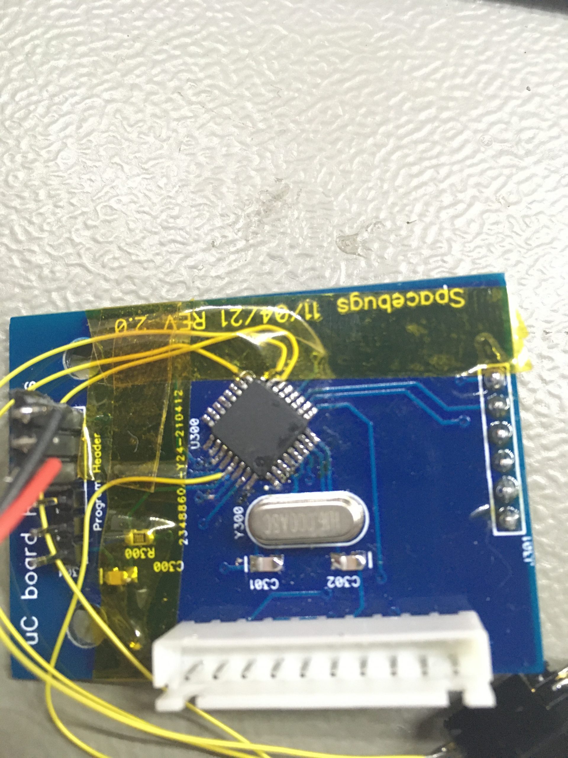
Once the new PCB’s were in, I started to solder all the IC and other parts. Once completed I realized that I didn’t think about adding a ISP header on the uC board.
So I had to improvise:
First soldering the wires to the micro controller
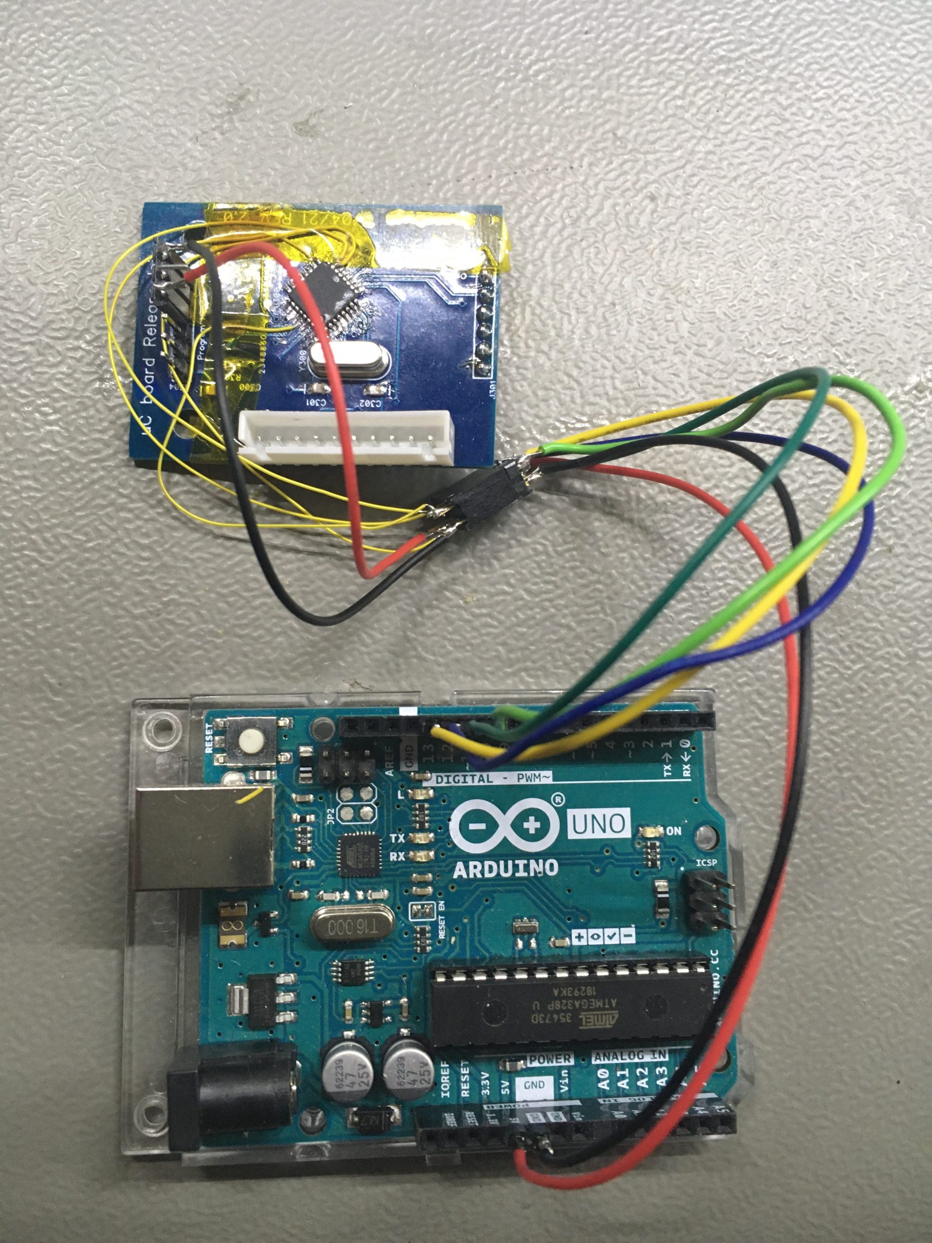
And finally after connecting all the wires together I could hook up a Arduino UNO as a ISP programmer. And could flash the boot loader. After that I could use the program header to upload the firmware.
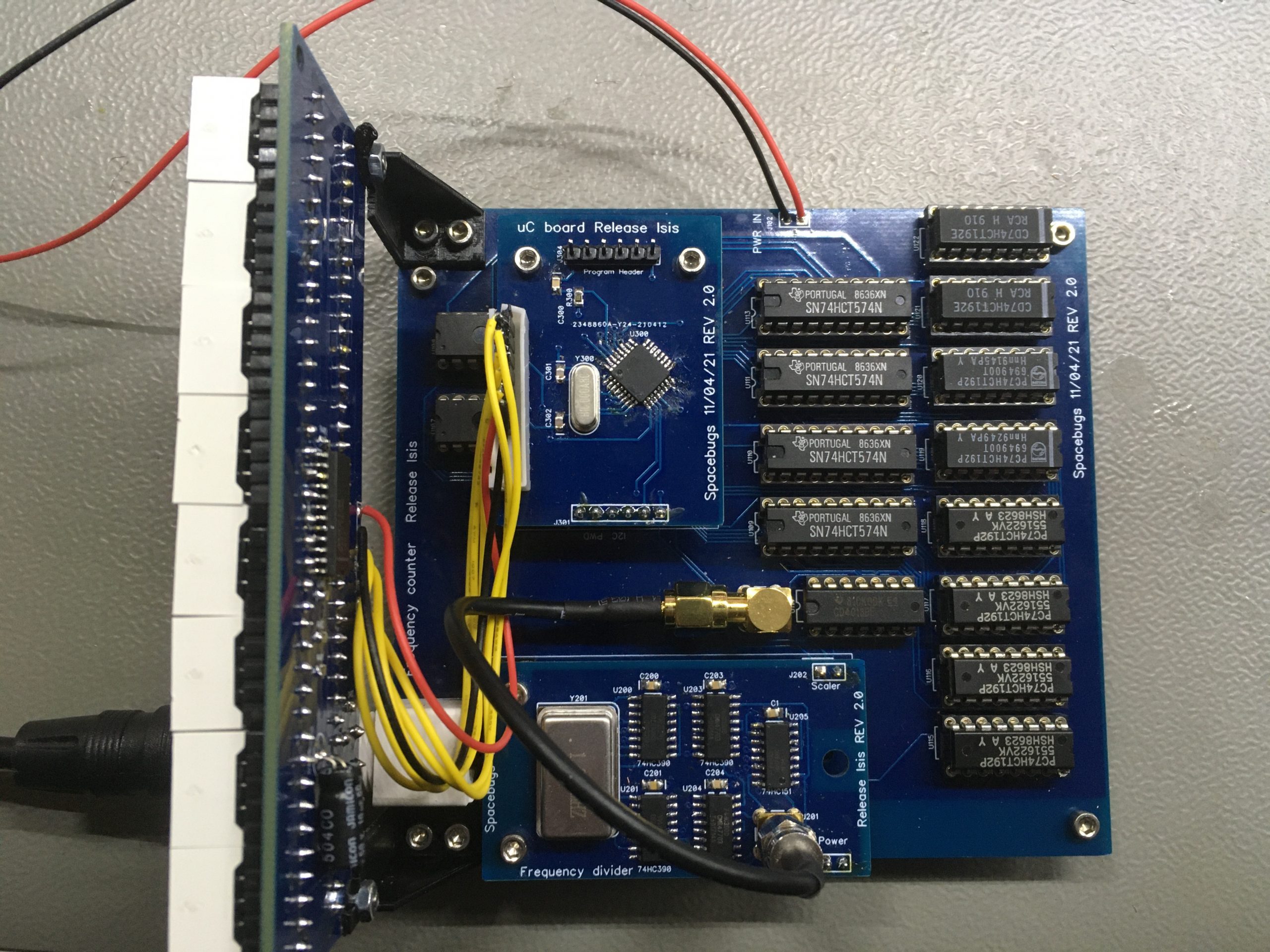
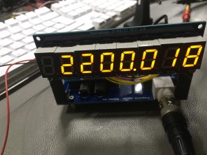
The end result
And this is how the end result looks like. I didn’t have cleaned the board, since I’m still testing, but to my surprise the counter was working the very first time. And the result looks like: