Introduction

In this article we take a look at how to configure an Ethernet Ring Protection Switching (ERPS) between a Cisco ASR 903 and two Juniper MX series routers (a MX 104 and MX 80). This article only shows how to configure the nodes. There are enough articles on the web to explain how ERPS (or G.8032) works.
Topology
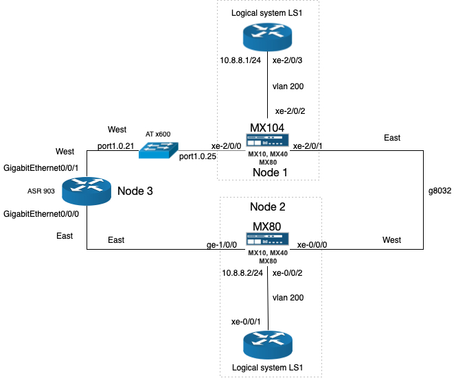
To configure ERPS a minimal of three devices are needed. To have two extra routers to test end-to-end connectivity two logic systems are created on the Juniper routers. The topology looks like:
Configure the RPL owner (node1)
To configuration of the RPL owner, the interfaces are configured first:
set interfaces xe-2/0/0 description "Connection to ASR903 gi-0/0/1"
set interfaces xe-2/0/0 vlan-tagging
set interfaces xe-2/0/0 encapsulation flexible-ethernet-services
set interfaces xe-2/0/0 unit 1 family bridge interface-mode trunk
set interfaces xe-2/0/0 unit 1 family bridge vlan-id-list 100-1000
set interfaces xe-2/0/1 description "Connection to mx80 xe-0/0/0"
set interfaces xe-2/0/1 vlan-tagging
set interfaces xe-2/0/1 encapsulation flexible-ethernet-services
set interfaces xe-2/0/1 unit 1 family bridge interface-mode trunk
set interfaces xe-2/0/1 unit 1 family bridge vlan-id-list 100-1000
Next the protection group is configured:
set protocols protection-group ethernet-ring pg101 node-id 00:01:01:00:00:01
set protocols protection-group ethernet-ring pg101 ring-protection-link-owner
set protocols protection-group ethernet-ring pg101 east-interface control-channel vlan 100
set protocols protection-group ethernet-ring pg101 east-interface control-channel xe-2/0/1.1
set protocols protection-group ethernet-ring pg101 east-interface ring-protection-link-end
set protocols protection-group ethernet-ring pg101 west-interface control-channel vlan 100
set protocols protection-group ethernet-ring pg101 west-interface control-channel xe-2/0/0.1
set protocols protection-group ethernet-ring pg101 data-channel vlan 200
set protocols protection-group ethernet-ring pg101 data-channel vlan 300
Next the virtual switch is configured:
set routing-instances vs instance-type virtual-switch
set routing-instances vs interface xe-2/0/0.1
set routing-instances vs interface xe-2/0/1.1
set routing-instances vs interface xe-2/0/2.200
set routing-instances vs bridge-domains bd1 vlan-id 100
set routing-instances vs bridge-domains bd200 vlan-id 200
set routing-instances vs bridge-domains bd300 vlan-id 300
The configuration of the logical system is as follows:
The physical interface is a back-to-back connection to another physical interface on the same router:
set interfaces xe-2/0/3 description "Back-to-back connection to xe-2/0/2"
set interfaces xe-2/0/3 vlan-tagging
set interfaces xe-2/0/3 encapsulation flexible-ethernet-services
set interfaces xe-2/0/3 gigether-options auto-negotiation
set logical-systems LS1 interfaces xe-2/0/3 unit 200 vlan-id 200
set logical-systems LS1 interfaces xe-2/0/3 unit 200 family inet address 10.8.8.1/24
Configuration of Node2
The configuration is almost similar, except there can only be one RPL owner in the ring. So this node is configured as a normal node.
The ring interfaces are configured first:
set interfaces xe-0/0/0 description "Connection to mx104 xe-20/0/1"
set interfaces xe-0/0/0 vlan-tagging
set interfaces xe-0/0/0 encapsulation flexible-ethernet-services
set interfaces xe-0/0/0 unit 1 family bridge interface-mode trunk
set interfaces xe-0/0/0 unit 1 family bridge vlan-id-list 100-1000
set interfaces ge-1/0/0 description "Connection to ASR903 gi-0/0/0"
set interfaces ge-1/0/0 vlan-tagging
set interfaces ge-1/0/0 encapsulation flexible-ethernet-services
set interfaces ge-1/0/0 unit 1 family bridge interface-mode trunk
set interfaces ge-1/0/0 unit 1 family bridge vlan-id-list 100-1000
The configuration of the protection group is as follows:
set protocols protection-group ethernet-ring pg102 east-interface control-channel vlan 100
set protocols protection-group ethernet-ring pg102 east-interface control-channel ge-1/0/0.1
set protocols protection-group ethernet-ring pg102 west-interface control-channel vlan 100
set protocols protection-group ethernet-ring pg102 west-interface control-channel xe-0/0/0.1
set protocols protection-group ethernet-ring pg102 data-channel vlan 200
set protocols protection-group ethernet-ring pg102 data-channel vlan 300
The configuration of the virtual switch:
set routing-instances vs instance-type virtual-switch
set routing-instances vs interface xe-0/0/0.1
set routing-instances vs interface xe-0/0/2.200
set routing-instances vs interface ge-1/0/0.1
set routing-instances vs bridge-domains bd1 vlan-id 100
set routing-instances vs bridge-domains bd200 vlan-id 200
set routing-instances vs bridge-domains bd300 vlan-id 300
The logical system configuration on this node, needs two physical interfaces. To achieve this, the interfaces xe-0/0/1 and xe-0/0/2 are connected back-to-back:
set interfaces xe-0/0/1 description "Back to back connection to xe-0/0/2"
set interfaces xe-0/0/1 vlan-tagging
set interfaces xe-0/0/1 encapsulation flexible-ethernet-services
set interfaces xe-0/0/2 description "Back to back connection to xe-0/0/1"
set interfaces xe-0/0/2 vlan-tagging
set interfaces xe-0/0/2 encapsulation flexible-ethernet-services
set interfaces xe-0/0/2 unit 200 family bridge interface-mode trunk
set interfaces xe-0/0/2 unit 200 family bridge vlan-id-list 200
The logical system is configured as:
set logical-systems LS1 interfaces xe-0/0/1 unit 200 vlan-id 200
set logical-systems LS1 interfaces xe-0/0/1 unit 200 family inet address 10.8.8.2/24
The configuration of node3 (Cisco ASR903)
The configuration start with configuring the g8032 part:
ethernet cfm ieee
ethernet cfm global
ethernet cfm domain g8032_domain level 0
service g8032_domain evc evc_name vlan 100 direction down
continuity-check
continuity-check interval 3.3ms
!
!
ethernet ring g8032 profile g8032_profile
 timer wtr 1
!
ethernet ring g8032 g8032_ring
 port0 interface GigabitEthernet0/0/1
 port1 interface GigabitEthernet0/0/0
 instance 1
  profile g8032_profile
 inclusion-list vlan-ids 100,150-2999
 aps-channel
  level 0
  port0 service instance 1
  port1 service instance 1
  !
 !
!
ethernet evc evc_name
!
Next configure the bridge domains:
bridge-domain 100
bridge-domain 200
bridge-domain 300
Next the ring interfaces are configured:
!
interface GigabitEthernet0/0/0
 no ip address
 negotiation auto
 service instance 1 ethernet evc_name
 encapsulation dot1q 100
 bridge-domain 100
 cfm mep domain g8032_domain mpid 2
  continuity-check static rmep
  rmep mpid 1
!
service instance trunk 1000 ethernet
 encapsulation dot1q 150-2999
 rewrite ingress tag pop 1 symmetric
 bridge-domain from-encapsulation
 !
!
interface GigabitEthernet0/0/1
 no ip address
 negotiation auto
 service instance 1 ethernet evc_name
 encapsulation dot1q 100
 bridge-domain 100
  cfm mep domain g8032_domain mpid 1
   continuity-check static rmep
   rmep mpid 2
!
service instance trunk 1000 ethernet
 encapsulation dot1q 150-2999
 rewrite ingress tag pop 1 symmetric
 bridge-domain from-encapsulation
 !
!
Verifying the configuration
On the node1 use the following commands to verify if the ring is working:
show protection-group ethernet-ring configuration

Ethernet Ring configuration information for protection group pg101

G8032 Compatibility Version : 2
East interface (interface 0) : xe-2/0/1.1
West interface (interface 1) : xe-2/0/0.1
Restore interval : 5 minutes
Wait to Block interval : 5 seconds
Guard interval : 500 ms
Hold off interval : 0 ms
Node ID : 00:01:01:00:00:01
Ring ID (1 ... 239) : 1
Node role (normal/rpl-owner/rpl-neighbour) : rpl-owner
Node RPL end : east-port
Revertive mode of operation : 1
RAPS Tx Dot1p priority (0 .. 7) : 0
Node type (normal/open/interconnection) : Normal
Control Vlan : 100
Physical Ring : No
Data Channel Vlan(s) : 200,300
Next check the ring aps status:
run show protection-group ethernet-ring aps
Ethernet Ring Request/state RPL Blocked No Flush BPR Originator Remote Node ID
pg101 NR Yes No 0 Yes NA
Perform the same commands on node2:
show protection-group ethernet-ring configuration

Ethernet Ring configuration information for protection group pg102

G8032 Compatibility Version : 2
East interface (interface 0) : ge-1/0/0.1
West interface (interface 1) : xe-0/0/0.1
Restore interval : 5 minutes
Wait to Block interval : 5 seconds
Guard interval : 500 ms
Hold off interval : 0 ms
Node ID : A8:D0:E5:59:4E:E8
Ring ID (1 ... 239) : 1
Node role (normal/rpl-owner/rpl-neighbour) : normal
Revertive mode of operation : 1
RAPS Tx Dot1p priority (0 .. 7) : 0
Node type (normal/open/interconnection) : Normal
Control Vlan : 100
Physical Ring : No
Data Channel Vlan(s) : 200,300
run show protection-group ethernet-ring aps
Ethernet Ring Request/state RPL Blocked No Flush BPR Originator Remote Node ID
pg102 NR Yes No 0 No 00:01:01:00:00:01
On node3:
show ethernet ring g8032 configuration

Ethernet ring g8032_ring
Port0: GigabitEthernet0/0/1 (Monitor: GigabitEthernet0/0/1)
Port1: GigabitEthernet0/0/0 (Monitor: GigabitEthernet0/0/0)
Exclusion-list VLAN IDs:
Open-ring: no
Instance 1
Description:
Profile: g8032_profile
RPL:
Inclusion-list VLAN IDs: 100,150-2999
APS channel
Level: 0
Port0: Service Instance 1
Port1: Service Instance 1
State: configuration resolved
Next check the status:
show ethernet ring g8032 status
Ethernet ring g8032_ring instance 1 is Normal Node node in Idle State
Port0: GigabitEthernet0/0/1 (Monitor: GigabitEthernet0/0/1)
APS-Channel: GigabitEthernet0/0/1
Status: Non-RPL
Remote R-APS NodeId: 0001.0100.0001, BPR: 0
Port1: GigabitEthernet0/0/0 (Monitor: GigabitEthernet0/0/0)
APS-Channel: GigabitEthernet0/0/0
Status: Non-RPL
Remote R-APS NodeId: 0001.0100.0001, BPR: 0
APS Level: 0
Profile: g8032_profile
WTR interval: 1 minutes
Guard interval: 500 milliseconds
HoldOffTimer: 0 seconds
Revertive mode
On node1 ping is done from the the logical system to the logical system on node2:
ping logical-system LS1 10.8.8.2 count 5
PING 10.8.8.2 (10.8.8.2): 56 data bytes
64 bytes from 10.8.8.2: icmp_seq=0 ttl=64 time=1.128 ms
64 bytes from 10.8.8.2: icmp_seq=1 ttl=64 time=2.468 ms
64 bytes from 10.8.8.2: icmp_seq=2 ttl=64 time=1.004 ms
64 bytes from 10.8.8.2: icmp_seq=3 ttl=64 time=1.025 ms
64 bytes from 10.8.8.2: icmp_seq=4 ttl=64 time=1.340 ms

--- 10.8.8.2 ping statistics ---
5 packets transmitted, 5 packets received, 0% packet loss
round-trip min/avg/max/stddev = 1.004/1.393/2.468/0.551 ms