Cheap and low power network switches.. are they any good ?

Introduction

With higher energy costs, running a lab with network gear becomes a costly hobby. To keep costs down I decided to look at some cheaper switches, which low power consumption. While on that path, it would be very nice if the switches are fanless as well. Less noise. Which is good. The switches must be rack mountable.

The only problem is: I really don’t like the cheap Netgear, TP-LINK and Zyxel switches. I “grew up” with Extreme Networks , Foundry, Cisco and Allied Telesys switches. And yes, I don’t come close to HP switches, or 3Com switches for that matter. The time I had to deal with those, I always find them troublesome, and very user unfriendly. Well I digress, back to the subject at hand 🙂

I decided to buy the following three switches:

    • TP-Link TL-SG1016DE 16-Ports Gigabit Switch
    • Zyxel GS1900-24 24 + 2x SFP ports Gigabit switch
    • Zyxel XGS1930-28 24 1Gb 4x sfp+ 1/10Gb ports switch

The TP-Link switch is around 60 Euro’s, while the Zyxel GS1900 switch is around 100 Euro’s. The Zyxel XGS1930 is more expensive, since it’s a 10Gb capable switch, and comes around 360 euro’s which is still cheap, compared to Cisco, Extreme or Foundry switches.

Before diving into the switches, keep in mind this isn’t a review, and the article contains my (less then soft) opinions. And while I don’t like these low end switches it’s time to get out of my comfert zone, and see if I can make friends with these switches, and yes.. that won’t be easy 😉

The TP-Link TL-SG1016DE 16-Poorts Gigabit Switch

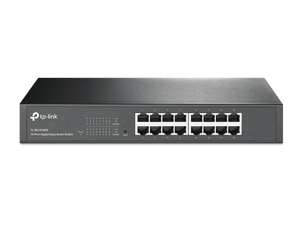
The first switch I had a look at is the TP-Link switch. And well, it works. It power usage is around 12Watt or so, and yes it’s fanless. It’s a small switch with a metal body. Which makes it more robust. The switch supports up to 32 dot1.q vlans, and has some other features as well. The main purpose for my use it to power my extensible Raspberry PI Cluster. If the switch is working reliable I might consider to buy a second one, so I can use it to connect my APC PDU’s to it.

After running the switch for months, it seems to do the business. For simple task this switch is usable. The main drawback is the lack of a way to list the mac address table. So In a real production network I won’t consider using this switch as a main switch. For a stub switch it might be ok.

The Zyxel GS1900-24

The (
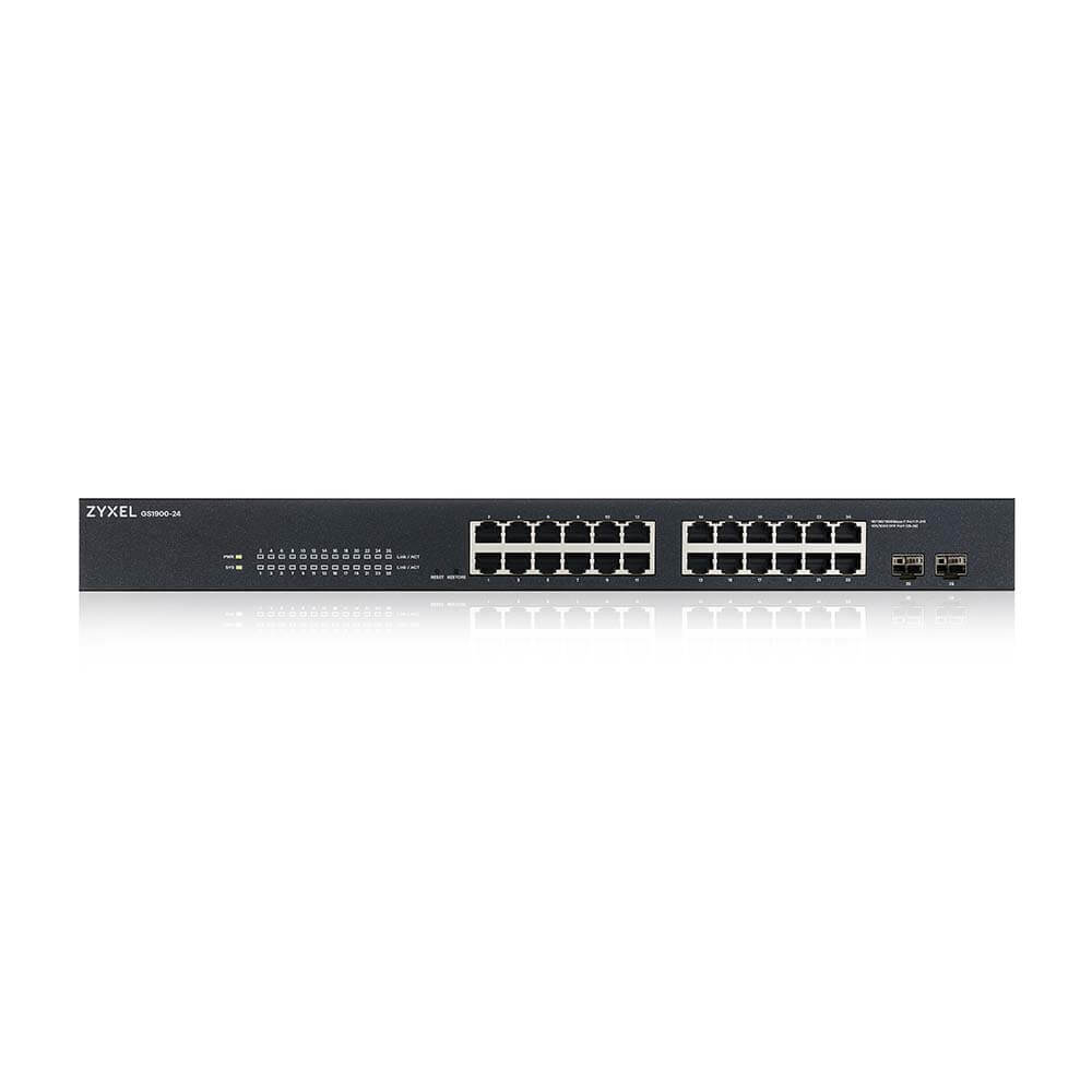
max) power consumption of this switch is 17.1 Watts according to the data-sheet. When first configuring the switch I stumbled across how Zyxel approaches vlan implementation. In one word: horrible. For example a trunk is used to “allow all unknown vlan’s to the switch to pass”. Which makes my skin crawl. In a serious network I NEVER want “unknown” vlans to pass between switches. Yeah sure.. it makes configuring links between switches so much easier… In my opinion: very bad practise, In a network configure things explicit, and don’t let devices do the configuration for you.

However, it’s possible to configure a port to accept “all”, and leave trunk disabled. Which means: accept only configured untagged and tagged frames on a port.

Apart from the vlan implementation, the web GUI interface is not that bad. The switch has a CLI, but it’s useless. You can’t configure the switch from the CLI. The CLI has a few commands available. Which makes me wonder why Zyxel puts any effort in supplying a CLI in the first place.

Another nice thing is that it’s possible to configure the management on a vlan interface. This also means that there is no need to have a untagged management vlan between switches. (I used to say: no untagged vlans on trunked ports, but .. well yeah..)

The only problem I had with this switch is when changing a port description, the port went down for a brief moment, but long enough to cause traffic interruption. In the latest firmware this issue is finally fixed.

Zyxel XGS1930-28

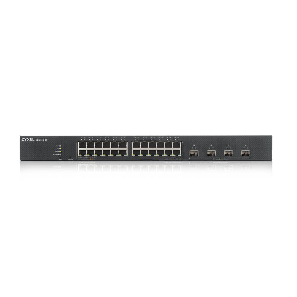
This switch is like all the previous switches fanless. The (max) power consumption of this switch is 24.6 Watts which is very low. When I booted the switch and logged into the GUI I was expecting an interface like the GS1900, but that was a disappointment. The vlan implementation is even worse. The trunk port foolish is the same, however to mark a port in a vlan as untagged, the option “Tx tagging” must be unset. Also to configure a vlan, this must be set to “Fixed”. The other option “Normal” is when using GVRP (Don’t use that… ) And the VLANID is now called “Vlan Group ID”..

Then there is the need to set a PVID (Port Vlan ID) on the port (untagged vlan) is poor software design (again in my opinion). And all the previous switches have this setting. The problem is that when not setting a PVID will set it to a default (vlan 1) which is bad, very bad. Vlan 1 shouldn’t be used a a regular vlan in a network.

In the “real” world a trunk port is configured with “untagged vlan none” for example, to prevent any untagged vlan (untagged ethernet frame) between switches. An access port is configured as “switchport access vlan vlanid”.

And the overall navigation in the GUI interface is not that good as the GS1900. It actually sucks in my opinion. For example: to configure a vlan, there are two sections to configure: “Static vlan Setup”and “Vlan Port Setup”. It’s not the end of the world, but having consistent interface layout between models would be nice. Of course in the end you get used to the user interface, but it doesn’t bring a smile on my face, while using it.

Like the GS1900, on this switch it’s also possible to configure the management interface as a vlan interface. Which is very neat.

This switch can also be configured by using the Zyxel’s clound “Nebula Control Centre (NCC). Which maybe the reason the user interface is different.  In my mind, using a cloud to configure your network is the best thing to do:  from a security point of view, and definitely from a continuity point of view (what happens when the Internet connection goes down, and you must remotely access your switches to configure them?

And yes this switch also has a CLI. There are more commands, but it’s not possible to configure the switch through this CLI. If it was possible to configure the switch through this CLI would add a lot of value to the switch.

The main reason for bying this switch is that it has four SFP+ ports, which can be used for SFP’s (1Gb) and SFP+ (1oGb). That gives this switch flexibility and a cheap way to add 10Gb to the network. Another benefit might be that the switch has basic layer 3 capabilities. I don’t know what the throughput when routing packets, but it adds more flexibility.

Overall conclusion

As a network engineer being used to work in ISP backbones and core networks I won’t like to see these switches. In a small business I guess it’s okay. However the TCO of these switches might be higher since real remote automation is not really possible.  The different GUI interfaces on the switches add to this. I guess if you don’t have any network knowledge, and going with to vlan implementation how Zyxel see it, might make it more easy to understand.  Enough over the dot1q vlan implementation details.

I use this switches for quite some time now, and they just work without any problems. The only rare problem I had that a Zyxel 19oo switch messed up it’s mac table. I saw mac addresses in vlan’s where they didn’t belong. Which messed up the mac addresses table on other switches as well. I “solved” that by rebooting the switch.  And making sure that vlan 1 was not configured on any used port. After this one time, it didn’t happen again.

A good question will be: Is it fair to compare these switches to enterprise switches ?

I guess not really when looking at the the price tag. When looking at the Zyxel switches and there feature set: then yes… maybe ? However performance wise.. I wouldn’t dare to compare.

If you look at these switches for what they are: for small business, and low power, the Zyxel switches provide a rich feature set, and are reliable. The TP-Link switch is the cheapest switch, and makes it ideal for a stub switch, and is also reliable. The real downside is not having the ability to view / clear the mac address table (at least I couldn’t find it).

What surprised me with Zyxel is the good documentation, and even links from the user interface to the Zyxel comunity forum. Good documentation, and having a community is a big plus.

The Zyxel GS1900 I really can recommand, if a 1Gb switch fits the bill. The switch is reliable, packs a lot of features, and the user web interface is easy to navigate, and very usable.

The Zyxel GS1930-28 strong points are the 4 SFP+ plus ports, the user interface is somewhat disappointing. But like the GS1900 it’s a capable switch, which brings a lot of features, and cheap way to 10Gig.

So in the end: yes these switches help to keep the costs down, by using less power. They work well, and in my lab I don’t need the horse power of Enterprise switches which consumes several hundreds of Watts. However from time to time I miss the the robust cli’s of the Cisco and alike switches, and the capabilities to automate stuff.


Ethernet Ring Protection Switching (G.8032) with Juniper and Cisco

Introduction

The Juniper and Cisco lab used.

In this article we take a look at how to configure an Ethernet Ring Protection Switching (ERPS) between a Cisco ASR 903 and two Juniper MX series routers (a MX 104 and MX 80). This article only shows how to configure the nodes. There are enough articles on the web to explain how ERPS (or G.8032) works.

Topology

To configure ERPS a minimal of three devices  are needed. To have two extra routers to test end-to-end connectivity two logic systems are created on the Juniper routers. The topology looks like:

Topology, click for larger picture, opens in a new tab.

Configure the RPL owner (node1)

To configuration of the RPL owner, the interfaces are configured first:

set interfaces xe-2/0/0 description "Connection to ASR903 gi-0/0/1"
set interfaces xe-2/0/0 vlan-tagging
set interfaces xe-2/0/0 encapsulation flexible-ethernet-services
set interfaces xe-2/0/0 unit 1 family bridge interface-mode trunk
set interfaces xe-2/0/0 unit 1 family bridge vlan-id-list 100-1000
set interfaces xe-2/0/1 description "Connection to mx80 xe-0/0/0"
set interfaces xe-2/0/1 vlan-tagging
set interfaces xe-2/0/1 encapsulation flexible-ethernet-services
set interfaces xe-2/0/1 unit 1 family bridge interface-mode trunk
set interfaces xe-2/0/1 unit 1 family bridge vlan-id-list 100-1000

Next the protection group is configured:

set protocols protection-group ethernet-ring pg101 node-id 00:01:01:00:00:01
set protocols protection-group ethernet-ring pg101 ring-protection-link-owner
set protocols protection-group ethernet-ring pg101 east-interface control-channel vlan 100
set protocols protection-group ethernet-ring pg101 east-interface control-channel xe-2/0/1.1
set protocols protection-group ethernet-ring pg101 east-interface ring-protection-link-end
set protocols protection-group ethernet-ring pg101 west-interface control-channel vlan 100
set protocols protection-group ethernet-ring pg101 west-interface control-channel xe-2/0/0.1
set protocols protection-group ethernet-ring pg101 data-channel vlan 200
set protocols protection-group ethernet-ring pg101 data-channel vlan 300

Next the virtual switch is configured:

set routing-instances vs instance-type virtual-switch
set routing-instances vs interface xe-2/0/0.1
set routing-instances vs interface xe-2/0/1.1
set routing-instances vs interface xe-2/0/2.200
set routing-instances vs bridge-domains bd1 vlan-id 100
set routing-instances vs bridge-domains bd200 vlan-id 200
set routing-instances vs bridge-domains bd300 vlan-id 300

The configuration of the logical system is as follows:

The physical interface is a back-to-back connection to another physical interface on the same router:

set interfaces xe-2/0/3 description "Back-to-back connection to xe-2/0/2"
set interfaces xe-2/0/3 vlan-tagging
set interfaces xe-2/0/3 encapsulation flexible-ethernet-services
set interfaces xe-2/0/3 gigether-options auto-negotiation
set logical-systems LS1 interfaces xe-2/0/3 unit 200 vlan-id 200
set logical-systems LS1 interfaces xe-2/0/3 unit 200 family inet address 10.8.8.1/24

Configuration of Node2

The configuration is almost similar, except there can only be one RPL owner in the ring. So this node is configured as a normal node.

The ring interfaces are configured first:

set interfaces xe-0/0/0 description "Connection to mx104 xe-20/0/1"
set interfaces xe-0/0/0 vlan-tagging
set interfaces xe-0/0/0 encapsulation flexible-ethernet-services
set interfaces xe-0/0/0 unit 1 family bridge interface-mode trunk
set interfaces xe-0/0/0 unit 1 family bridge vlan-id-list 100-1000
set interfaces ge-1/0/0 description "Connection to ASR903 gi-0/0/0"
set interfaces ge-1/0/0 vlan-tagging
set interfaces ge-1/0/0 encapsulation flexible-ethernet-services
set interfaces ge-1/0/0 unit 1 family bridge interface-mode trunk
set interfaces ge-1/0/0 unit 1 family bridge vlan-id-list 100-1000

The configuration of the protection group is as follows:

set protocols protection-group ethernet-ring pg102 east-interface control-channel vlan 100
set protocols protection-group ethernet-ring pg102 east-interface control-channel ge-1/0/0.1
set protocols protection-group ethernet-ring pg102 west-interface control-channel vlan 100
set protocols protection-group ethernet-ring pg102 west-interface control-channel xe-0/0/0.1
set protocols protection-group ethernet-ring pg102 data-channel vlan 200
set protocols protection-group ethernet-ring pg102 data-channel vlan 300

The configuration of the virtual switch:

set routing-instances vs instance-type virtual-switch
set routing-instances vs interface xe-0/0/0.1
set routing-instances vs interface xe-0/0/2.200
set routing-instances vs interface ge-1/0/0.1
set routing-instances vs bridge-domains bd1 vlan-id 100
set routing-instances vs bridge-domains bd200 vlan-id 200
set routing-instances vs bridge-domains bd300 vlan-id 300

The logical system configuration on this node, needs two physical interfaces. To achieve this, the interfaces xe-0/0/1 and xe-0/0/2 are connected back-to-back:

set interfaces xe-0/0/1 description "Back to back connection to xe-0/0/2"
set interfaces xe-0/0/1 vlan-tagging
set interfaces xe-0/0/1 encapsulation flexible-ethernet-services
set interfaces xe-0/0/2 description "Back to back connection to xe-0/0/1"
set interfaces xe-0/0/2 vlan-tagging
set interfaces xe-0/0/2 encapsulation flexible-ethernet-services
set interfaces xe-0/0/2 unit 200 family bridge interface-mode trunk
set interfaces xe-0/0/2 unit 200 family bridge vlan-id-list 200

The logical system is configured as:

set logical-systems LS1 interfaces xe-0/0/1 unit 200 vlan-id 200
set logical-systems LS1 interfaces xe-0/0/1 unit 200 family inet address 10.8.8.2/24

The configuration of node3 (Cisco ASR903)

The configuration start with configuring the g8032 part:

ethernet cfm ieee
ethernet cfm global
ethernet cfm domain g8032_domain level 0
service g8032_domain evc evc_name vlan 100 direction down
continuity-check
continuity-check interval 3.3ms
!
!
ethernet ring g8032 profile g8032_profile
 timer wtr 1
!
ethernet ring g8032 g8032_ring
 port0 interface GigabitEthernet0/0/1
 port1 interface GigabitEthernet0/0/0
 instance 1
  profile g8032_profile
 inclusion-list vlan-ids 100,150-2999
 aps-channel
  level 0
  port0 service instance 1
  port1 service instance 1
  !
 !
!
ethernet evc evc_name
!

Next configure the bridge domains:

bridge-domain 100
bridge-domain 200
bridge-domain 300

Next the ring interfaces are configured:

!
interface GigabitEthernet0/0/0
 no ip address
 negotiation auto
 service instance 1 ethernet evc_name
 encapsulation dot1q 100
 bridge-domain 100
 cfm mep domain g8032_domain mpid 2
  continuity-check static rmep
  rmep mpid 1
!
service instance trunk 1000 ethernet
 encapsulation dot1q 150-2999
 rewrite ingress tag pop 1 symmetric
 bridge-domain from-encapsulation
 !
!
interface GigabitEthernet0/0/1
 no ip address
 negotiation auto
 service instance 1 ethernet evc_name
 encapsulation dot1q 100
 bridge-domain 100
  cfm mep domain g8032_domain mpid 1
   continuity-check static rmep
   rmep mpid 2
!
service instance trunk 1000 ethernet
 encapsulation dot1q 150-2999
 rewrite ingress tag pop 1 symmetric
 bridge-domain from-encapsulation
 !
!

Verifying the configuration

On the node1 use the following commands to verify if the ring is working:

show protection-group ethernet-ring configuration

Ethernet Ring configuration information for protection group pg101

G8032 Compatibility Version : 2
East interface (interface 0) : xe-2/0/1.1
West interface (interface 1) : xe-2/0/0.1
Restore interval : 5 minutes
Wait to Block interval : 5 seconds
Guard interval : 500 ms
Hold off interval : 0 ms
Node ID : 00:01:01:00:00:01
Ring ID (1 ... 239) : 1
Node role (normal/rpl-owner/rpl-neighbour) : rpl-owner
Node RPL end : east-port
Revertive mode of operation : 1
RAPS Tx Dot1p priority (0 .. 7) : 0
Node type (normal/open/interconnection) : Normal
Control Vlan : 100
Physical Ring : No
Data Channel Vlan(s) : 200,300

Next check the ring aps status:

run show protection-group ethernet-ring aps
Ethernet Ring Request/state RPL Blocked No Flush BPR Originator Remote Node ID
pg101 NR Yes No 0 Yes NA

Perform the same commands on node2:

show protection-group ethernet-ring configuration

Ethernet Ring configuration information for protection group pg102

G8032 Compatibility Version : 2
East interface (interface 0) : ge-1/0/0.1
West interface (interface 1) : xe-0/0/0.1
Restore interval : 5 minutes
Wait to Block interval : 5 seconds
Guard interval : 500 ms
Hold off interval : 0 ms
Node ID : A8:D0:E5:59:4E:E8
Ring ID (1 ... 239) : 1
Node role (normal/rpl-owner/rpl-neighbour) : normal
Revertive mode of operation : 1
RAPS Tx Dot1p priority (0 .. 7) : 0
Node type (normal/open/interconnection) : Normal
Control Vlan : 100
Physical Ring : No
Data Channel Vlan(s) : 200,300
run show protection-group ethernet-ring aps
Ethernet Ring Request/state RPL Blocked No Flush BPR Originator Remote Node ID
pg102 NR Yes No 0 No 00:01:01:00:00:01

On node3:

show ethernet ring g8032 configuration

Ethernet ring g8032_ring
Port0: GigabitEthernet0/0/1 (Monitor: GigabitEthernet0/0/1)
Port1: GigabitEthernet0/0/0 (Monitor: GigabitEthernet0/0/0)
Exclusion-list VLAN IDs:
Open-ring: no
Instance 1
Description:
Profile: g8032_profile
RPL:
Inclusion-list VLAN IDs: 100,150-2999
APS channel
Level: 0
Port0: Service Instance 1
Port1: Service Instance 1
State: configuration resolved

Next check the status:

show ethernet ring g8032 status
Ethernet ring g8032_ring instance 1 is Normal Node node in Idle State
Port0: GigabitEthernet0/0/1 (Monitor: GigabitEthernet0/0/1)
APS-Channel: GigabitEthernet0/0/1
Status: Non-RPL
Remote R-APS NodeId: 0001.0100.0001, BPR: 0
Port1: GigabitEthernet0/0/0 (Monitor: GigabitEthernet0/0/0)
APS-Channel: GigabitEthernet0/0/0
Status: Non-RPL
Remote R-APS NodeId: 0001.0100.0001, BPR: 0
APS Level: 0
Profile: g8032_profile
WTR interval: 1 minutes
Guard interval: 500 milliseconds
HoldOffTimer: 0 seconds
Revertive mode

On node1 ping is done from the the logical system to the logical system on node2:

ping logical-system LS1 10.8.8.2 count 5
PING 10.8.8.2 (10.8.8.2): 56 data bytes
64 bytes from 10.8.8.2: icmp_seq=0 ttl=64 time=1.128 ms
64 bytes from 10.8.8.2: icmp_seq=1 ttl=64 time=2.468 ms
64 bytes from 10.8.8.2: icmp_seq=2 ttl=64 time=1.004 ms
64 bytes from 10.8.8.2: icmp_seq=3 ttl=64 time=1.025 ms
64 bytes from 10.8.8.2: icmp_seq=4 ttl=64 time=1.340 ms

--- 10.8.8.2 ping statistics ---
5 packets transmitted, 5 packets received, 0% packet loss
round-trip min/avg/max/stddev = 1.004/1.393/2.468/0.551 ms

How to create layer 2 trunk port and access vlans on a Juniper SRX

Introduction

Creating vlans on a Juniper SRX is not as straight forward if you’re used to Cisco gear for example. In this article I hope to explain how to create:

      • One port as a trunk port
      • Other ports as access port
      • Add a mgmt L3 interface

Creating the trunk port

Let’s first create the trunk port. The interface fe-0/0/0 is used as a uplink port to another switch, and this ports carriers multiple tagged vlans. And it carriers only tagged vlans. No untagged vlan is allowed on this port.

To configure the port as a trunk port, the  port-mode has to be set to “trunk” and the allowed vlans needs to be configured. In this case the tagged vlan id’s are: 100,102:

set interfaces fe-0/0/0 description UPLINK-BB-SLV-LAN-P1.0.12
set interfaces fe-0/0/0 unit 0 family ethernet-switching port-mode trunk
set interfaces fe-0/0/0 unit 0 family ethernet-switching vlan members vlan-102
set interfaces fe-0/0/0 unit 0 family ethernet-switching vlan members vlan-100

Note that the vlan names are used, which at this point still needs to be created. It’s also possible to specify the vlanid here:

set interfaces fe-0/0/0 description UPLINK-BB-SLV-LAN-P1.0.12
set interfaces fe-0/0/0 unit 0 family ethernet-switching port-mode trunk
set interfaces fe-0/0/0 unit 0 family ethernet-switching vlan members 102
set interfaces fe-0/0/0 unit 0 family ethernet-switching vlan members 100

Create the vlans

Creating the vlans is straightforward:

set vlans vlan-100 vlan-id 100
set vlans vlan-102 vlan-id 102

Create the access ports

Creating the access ports is just like creating a trunk port, accept the port-mode is set to .. yes you guessed it.. ‘access‘.  So let’s assume we want to set the ports fe0/0/01 – fe0/0/7 as access ports with vlan 102.

set interfaces fe-0/0/1 unit 0 family ethernet-switching port-mode access
set interfaces fe-0/0/1 unit 0 family ethernet-switching vlan members vlan-102
set interfaces fe-0/0/2 unit 0 family ethernet-switching port-mode access
set interfaces fe-0/0/2 unit 0 family ethernet-switching vlan members vlan-102
set interfaces fe-0/0/3 unit 0 family ethernet-switching port-mode access
set interfaces fe-0/0/3 unit 0 family ethernet-switching vlan members vlan-102
set interfaces fe-0/0/4 unit 0 family ethernet-switching port-mode access
set interfaces fe-0/0/4 unit 0 family ethernet-switching vlan members vlan-102
set interfaces fe-0/0/5 unit 0 family ethernet-switching port-mode access
set interfaces fe-0/0/5 unit 0 family ethernet-switching vlan members vlan-102
set interfaces fe-0/0/6 unit 0 family ethernet-switching port-mode access
set interfaces fe-0/0/6 unit 0 family ethernet-switching vlan members vlan-102
set interfaces fe-0/0/7 unit 0 family ethernet-switching port-mode access
set interfaces fe-0/0/7 unit 0 family ethernet-switching vlan members vlan-102

However, this is a lot of typing. With junos it’s possible to use an interface range configuration. This is somewhat different to Cisco’s IOS or IOS-XE.

To use a interface range, first create a interface range name. For example ‘access-ports’. Then the name ‘access-ports’ can be used to add members. Next the properties of the interfaces can be assigned.

This might sound complex, but it’s quite simple and easy to use (and powerful):

set interfaces interface-range access-ports member "fe-0/0/[1-7]"
set interfaces interface-range access-ports unit 0 family ethernet-switching port-mode access
set interfaces interface-range access-ports unit 0 family ethernet-switching vlan members vlan-102

Assign the interfaces to the vlans

In the last step, the interfaces needs to be assigned to the vlans. So to assign the trunk port and access port to vlan 102 we need to do the following:

set vlans vlan-102 interface fe-0/0/0.0
set vlans vlan-102 interface fe-0/0/1.0
set vlans vlan-102 interface fe-0/0/2.0
set vlans vlan-102 interface fe-0/0/3.0
set vlans vlan-102 interface fe-0/0/4.0
set vlans vlan-102 interface fe-0/0/5.0
set vlans vlan-102 interface fe-0/0/6.0
set vlans vlan-102 interface fe-0/0/7.0

Note: the interfaces added are added by using the unit number, which is 0 here.

The above could be done in one command: simply by using the previous defined interface range ‘access-port’:

set vlans vlan-102 interface access-ports

When the an interface range is used, the trunk ports needs to be added as well:

set vlans vlan-102 interface fe-0/0/0.0

At this point the configuration can be committed:

commit

At this point, the layer 2 configuration is complete. The most easiest way to check if everything works is to look at the mac table. The command to do this is:

show ethernet-switching mac-learning-log

If everything is well it’s shows the learned mac addresses.

Create a Layer 3 management interface

To manage the SRX, it might be handy to have management vlan. In this case vlan id 100 is used.

To add a layer 3 vlan interface the next configuration is needed:

First create the vlan interface:

set interfaces vlan unit 100 family inet address 10.90.0.14/24

Next the interface can be added to the vlan 100:

set vlans vlan-100 l3-interface vlan.100

To activate to configuration don’t forget to do a commit:

commit

How to connect GNS3 virtual appliance to OSX Mojave

How to connect GNS3 virtual appliance to OSX Mojave

When working with GNS3 lab, it’s easy to connect the virtual lab to the internet. This is simply done by using the “cloud” and connect it to a wired interface (wifi adapter won’t work).

The problem with this setup is that the virtual GNS3 lab is not accessible from the local system. In my case a Macbook Pro. And since I almost use wifi connection, I don’t have a physical interface to bind to. When using virtual appliances which in turn have web GUI’s, it can be very annoying when those devices can’t be reached from a browser on the local system.

Searching for a solution, I came across a solution to install a tuntap package, but this package won’t work on Mojave.

Luckily there is an other and easy solution when using GNS3 with vmware Fusion. Once GNS3 and vmware Fusion is installed, and started, Fusion creates so called “vmnet” interfaces. This may also be the case when using VirtualBox, but I haven’t tested it.

So keep in mind that this solution has a short coming, being that there is no connection to the Internet. Depending on the local network setup, it should be possible to go through the trouble of setting op routes. But in my case I don’t need Internet access from the virtual lab.

These interfaces have an ip address (let’s say 192.168.4.1) When placing the “cloud” in GNS3, just add a vmnet interface:

Make sure to tick the box “Show special Ethernet interfaces”

Select the vmnet interface from the pulldown menu and click on the “Add” button. The vmnet interface should now appear in the box below, where the interface can be selected.


Next connect the vmnet interface to the cloud, and connect the virtual appliance to the cloud. Give the virtual appliance an ip adres in the same subnet (192.168.4.x/24) The virtual lab should now be reachable from the local system.

Password recovery on SRX 100

Password recovery on Juniper SRX 100

One day when I arrived at the office I did find a little blue box on my desk, which turned out to be a Juniper SRX 100 firewall. While looking at this tiny device I remembered that a colleague of my told me he would give a Juniper SRX to me.

And since I really like hardware, even the small boxes 🙂 I’m very pleased he brought this SRX, and give it to me.. So a big thanks!

Up for a challenge

At the end of the day, well actually later that evening, after I had something to eat, it was time to power the SRX on. The original adapter was missing, but since I got a box full of adapters , finding the right adapter shouldn’t be a problem. And sure enough.. after a while I came up with an adapter which delivers 12V and 1.5A.

The adapter has its ground (-) on the outerside, and the plus (+) on the middle pin.

The SRX needs 12V and 1A, so this adapter will do just fine. After searching for a console cable (a standard Cisco console cable just works) I connected the SRX, plugged in the console and power, and switched the device on.

After a few moments I was greeted with a banner, telling me the device once belonged to Ziggo. And that also told me right away that a simple password recovery is not going to work.

The SRX has a reset button, which can be used to reset the password..  However through a configuration setting this button can be disabled.. And since this device once belong to Ziggo, I know for sure that they disabled this button. Of course I tried the reset button.. and yes.. it did nothing at all.

So how to get into this device….

Using an USB device

Their is only one way around this.. and that is: installing / upgrading the SRX. This can be done by putting a Junos image (.tgz file) on a USB device, or putting the image on a tftp server.

The first problem is: how to get a Junos file.. Well I don’t have a support contract with Juniper.. so I had to google for a while but finally found a torrent file.

This is however not recommended, for one: it’s illegal. And two: the image can be tempered with, and could hide some nasty stuff.  I don’t like the illegal stuff, and in my lab I can perfectly live with the possible security risk.

Anyway, once I got the software I formatted a USB stick, and copied the junos image. After inserting the usb stick in the SRX 100 I interrupted the boot sequence. This can be done by hitting the spacebar while connected to the serial console at boot time.

Once the boot process was interrupted I was looking for a command “install”. Unfortunately this command was not present in the u-shell.

So I rebooted pressing the reset button while booting, and this activated a second boot partition. This version had the install command.

From there I tried o load the image from the USB stick.. but that didn’t work. Well not to worry.. I got a tftp server.. Copied over the junos image to my tftp server and started a install by tftp..


And that worked 🙂 After completing the upgrade.. I can logging with the root user and no password.