Nanovna black-and-gold unstable after firmware upgrade. How to fix?

Introduction

After getting a Nanovna I tried to upgrade the firmware and that where I find out the enormous amount of different hardware versions, making it almost impossible to find out which firmware is the right one. The question is: where to start?

Where to start?

The Nanovna is a complex device, and the different hardware types, makes it even more complex to update the firmware. So when getting a Nanovna the learning curve can be quite steep. And when you finally figured out which firmware to get,   it’s not funny to discover the firmware just installed is making the Nanovna unstable.

When getting a Nanovna there are a couple of resouces. For instance subscribe to the different Nanovna groups.io:

      • nanovna user (https://groups.io/g/nanovna-users)
      • nanoVNA V2 Users Group (https://groups.io/g/NanoVNAV2)

There are a lot of posting, wiki’s to go through. To understand more about the hardware versions of the Nanovna check out:

Unstable firmware

The Nanovna I got is a so called “black-and-gold” version. This is a clone based on the Nanovna version 2 made by HCXQS in collaboration with OwOComm. According to their site: https://nanorfe.com/nanovna-v2.html the latest official firmware version is ‘20201013’. After installing this version I noticed that when moving the markers around, the Nanovna crashes. The only way to get it going again, is to power it off and on again.

There is also “alternative firmware” for these devices. Figuring out which firmware is for what hardware version, is almost impossible. I discovered,  that it’s relativity safe to try out fimware. If the device doesn’t boot or the firmware is misbehaving just install another one. The device can be boot into “DFU”, from there new firmware can be installed. In my case I use the vna_qt application. Once the device is in DFU mode, and I connect it to the vna_qt application it asks me if I want to install new firmware.

So after searching through the Nanovna users group I found the following firmware: https://groups.io/g/NanoVNAV2/topic/firmware_for_v2_it_contain/81847314?p=,,,20,0,0,0::recentpostdate%2Fsticky,,,20,2,20,81847314. This seems older formware, but it works After uploading it the Nanovna works great :-).

I tried to compile the firmware myself, tried a lot of things, unfortunately I always end up with a white screen.
Working on a older project – making a frequency counter

  Introduction

Since the Corona virus pandemic I got some more free time on my hands in the weekend and decided to blew off the dust from a project I was working on. This project involves designing and making a frequency counter. This project is more about learning on how to make a modular design.

The frequency counter modules

The frequency counter has the following modules:

      • A main board which holds all the modules, the counter itself and the display buffer
      • A Divider module. This modules controls the gate time (which can be set in three steps)
      • A Micro Controller (uC) module. This module controls the multiplexing of the display as well as other features such as handling the button pushes on the front panel. (there are two buttons)
      • A Display module. This module holds the 7 segment displays as well as  a max7219 which takes care of the multiplexing.
      • A power module which provides power to the frequency counter. This module is yet to be designed.

The things I wanted to improve

In the first versions the modules used wires to interconnect with the main-board. In this version I wanted the modules to interconnect to the main-board directly, without using wires.

Secondly I wanted to reroute the PCB’s. Since the start of the project I used auto router to route the traces. Since it was one of the first PCB I created. Since I learned a lot more about PCB design I decided to route all the trace manually.

And I wanted to learn more about SMD soldering so I decided to change some IC’s from a DIP package to a smd package. Which means I had to swap connections to other pins, since the pin numbers are not always the same.

And last I wanted to have the ability to mount the display on to the main-board.


Testing the changes made

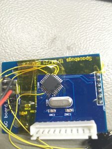
Once the new PCB’s were in, I started to solder all the IC and other parts. Once completed I realized that I didn’t think about adding a ISP header on the uC board.

So I had to improvise:

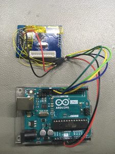
First soldering the wires to the micro controller

And finally after connecting all the wires together I could hook up a Arduino UNO as a ISP programmer. And could flash the boot loader. After that I could use the program header to upload the firmware.

The end result

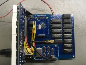
And this is how the end result looks like. I didn’t have cleaned the board, since I’m still testing, but to my surprise the counter was working the very first time. And the result looks like:

Testing max data throughput on a BreadBoard

Testing max data throughput on a BreadBoard

After I repaired the Tektronix Bert tester PB200 I can finally do a test which I wanted to do for a long time. And that is to test the max data throughput of a breadboard. So in other words: What is the max speed at which data can travel through a breadboard (BB) without any errors ?

I came up with two tests:

      • The first test is to use a couple of rows on the BB
      • The second test is to use a power rail

Preparing the first test

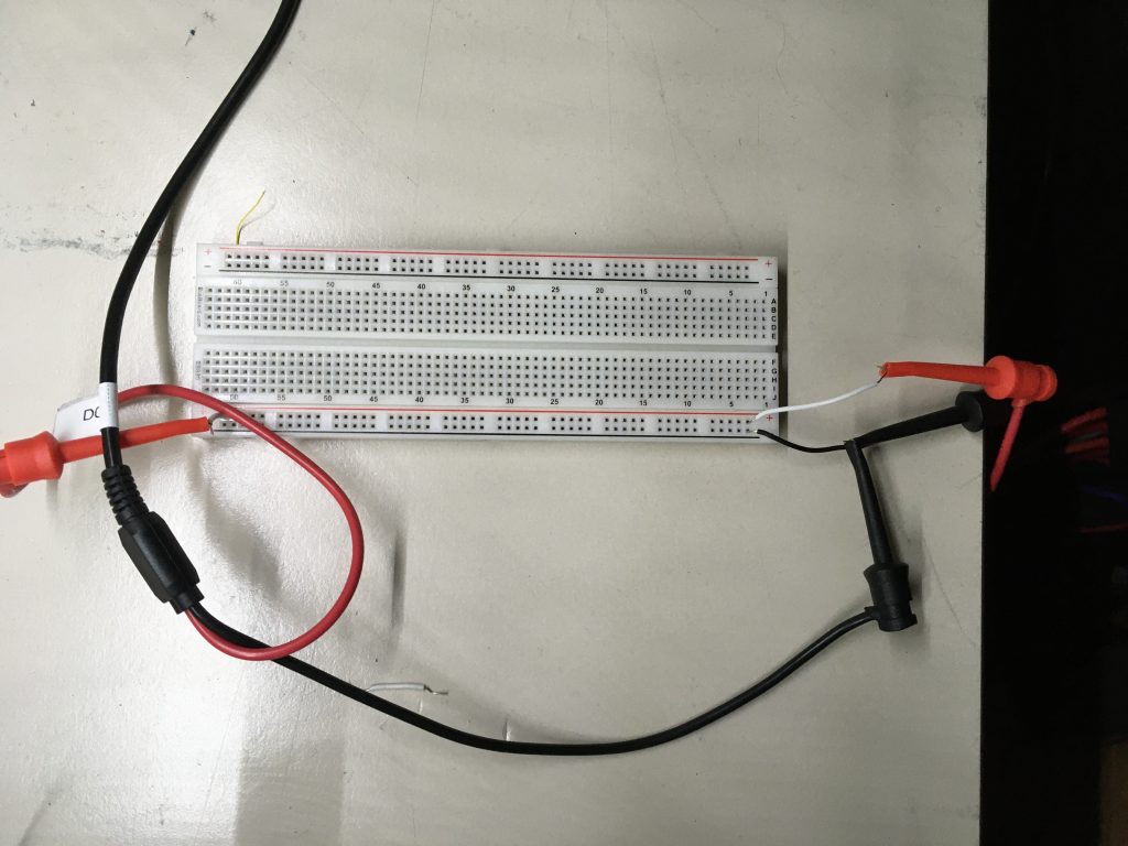
The test setup is quite easy, just a few wires on a bread board. I didn’t put the wires across the whole length of the BB, at that point a lot of other stuff comes into play. Just by adding a few wires I get (roughly) an idea what the impact of extra connections is.

And to get an initial impression I started the test with just connecting the probes to a BB and measure the data transfer. This gives me a base line of 80 Mhz.

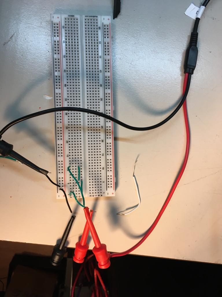
Next I prepare the BB as follows:

As can be seen just a couple of connections to generate some contact resistance. The BB and wires will add some capacitance too.

The test results of the first test

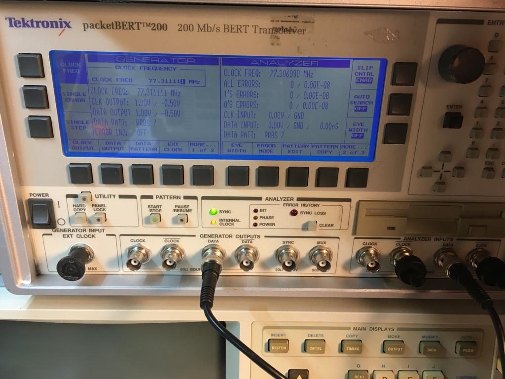
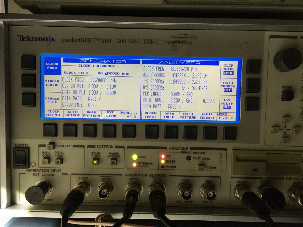
This results in:

It’s somewhat hard to read from the reflecting screen, but the max throughput I got after running this test for a couple of hours is around 77Mhz. So compared to the earlier test, adding a couple of wires resulted in a loss of 11Mhz. Which is quite a loss.

But note that this is is quick test. I didn’t use a loaf of 50Ohms, and I used a good quality BB (BusBoard Prototype Systems BB830).

Setting up the second test

The second test looks like:

Once this is setup I ran the test. When a test fails it looks like:

When an error occurs I lower the frequency, and reset the error. And the end

Results of the second test

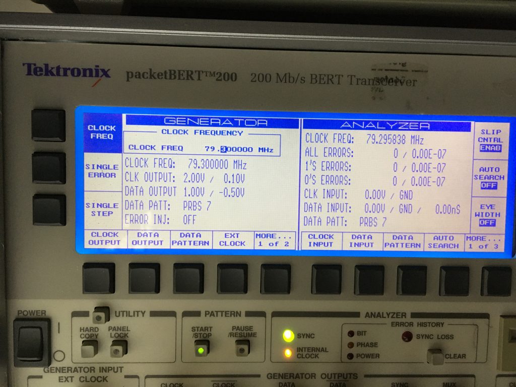
I could get a max throughput of:

So it’s very close to 80 Mhz. However in a real case scenario don’t expect to send data across with this high speeds. In reality I ques somewhere around 10 Mhz till 40Mhz is more realistic.

Hello world!

This site was previously known as “spacebugs”. That site has been taken down. Long story. One day I will come to that. For now, after years I’m back.  And I’m planning to get all the old articles restored to this site. And of course some new content..

Hades.