Testing max data throughput on a BreadBoard
After I repaired the Tektronix Bert tester PB200 I can finally do a test which I wanted to do for a long time. And that is to test the max data throughput of a breadboard. So in other words: What is the max speed at which data can travel through a breadboard (BB) without any errors ?
I came up with two tests:
-
-
- The first test is to use a couple of rows on the BB
- The second test is to use a power rail
-
Preparing the first test
The test setup is quite easy, just a few wires on a bread board. I didn’t put the wires across the whole length of the BB, at that point a lot of other stuff comes into play. Just by adding a few wires I get (roughly) an idea what the impact of extra connections is.
And to get an initial impression I started the test with just connecting the probes to a BB and measure the data transfer. This gives me a base line of 80 Mhz.
Next I prepare the BB as follows:
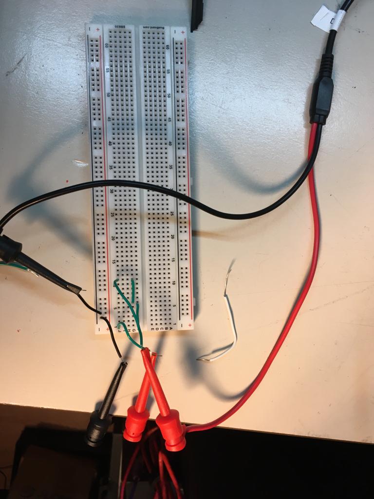 As can be seen just a couple of connections to generate some contact resistance. The BB and wires will add some capacitance too.
The test results of the first test
This results in:
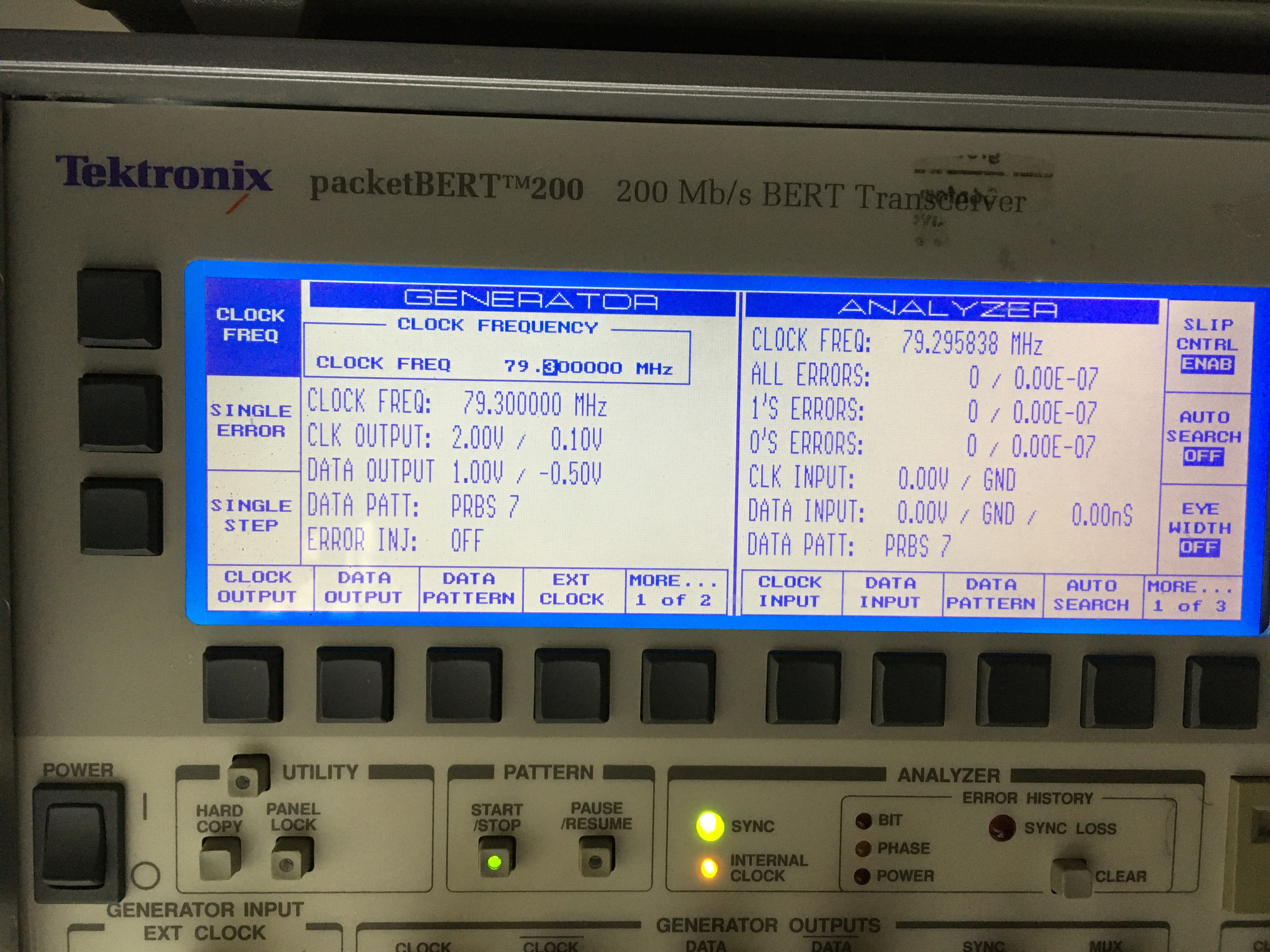
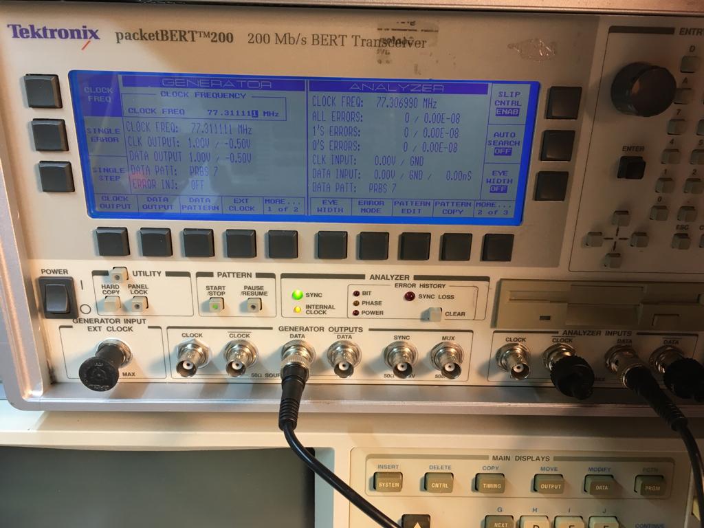 It’s somewhat hard to read from the reflecting screen, but the max throughput I got after running this test for a couple of hours is around 77Mhz. So compared to the earlier test, adding a couple of wires resulted in a loss of 11Mhz. Which is quite a loss.
But note that this is is quick test. I didn’t use a loaf of 50Ohms, and I used a good quality BB (BusBoard Prototype Systems BB830).
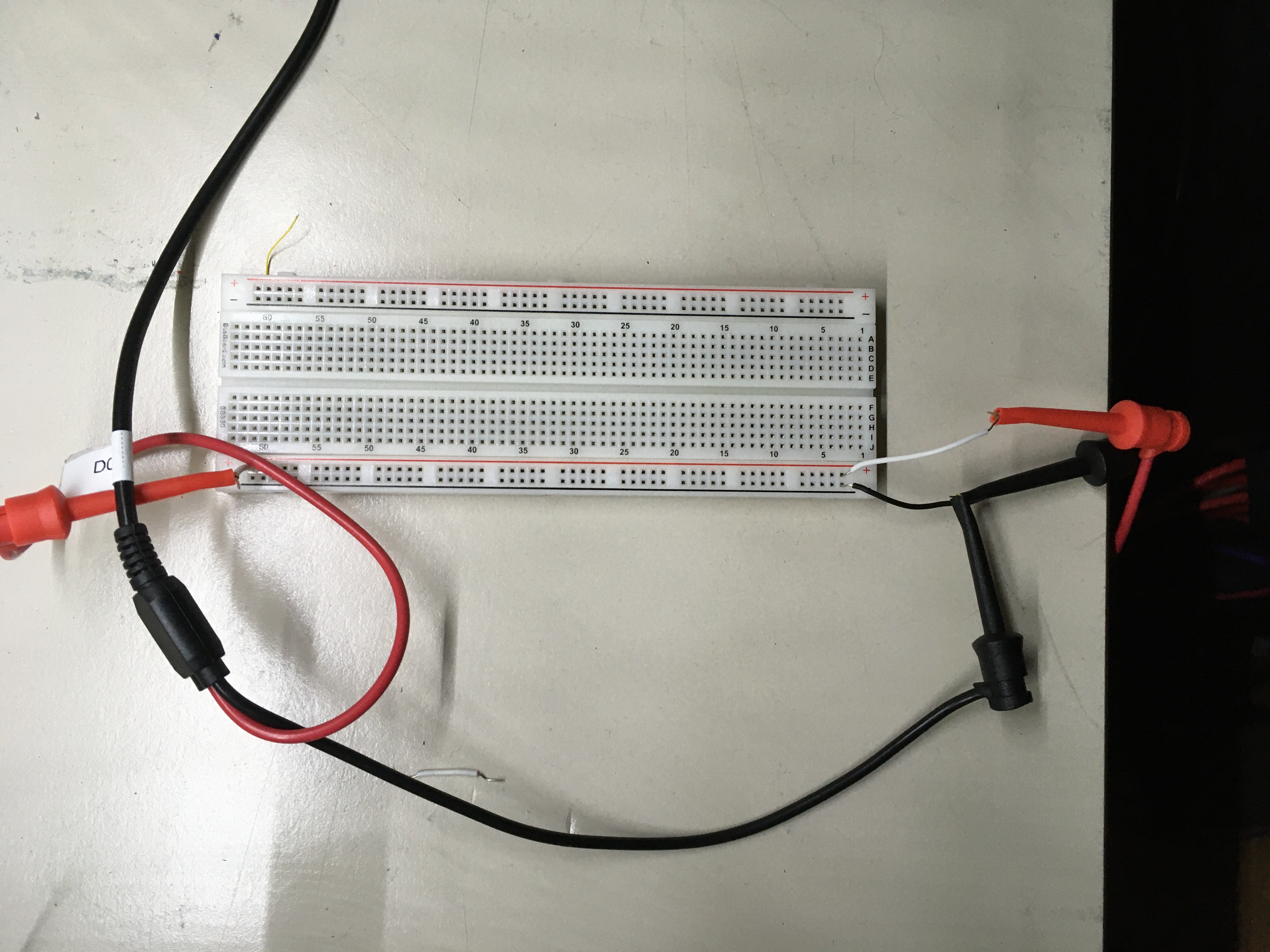
Setting up the second test
The second test looks like:
Once this is setup I ran the test. When a test fails it looks like:
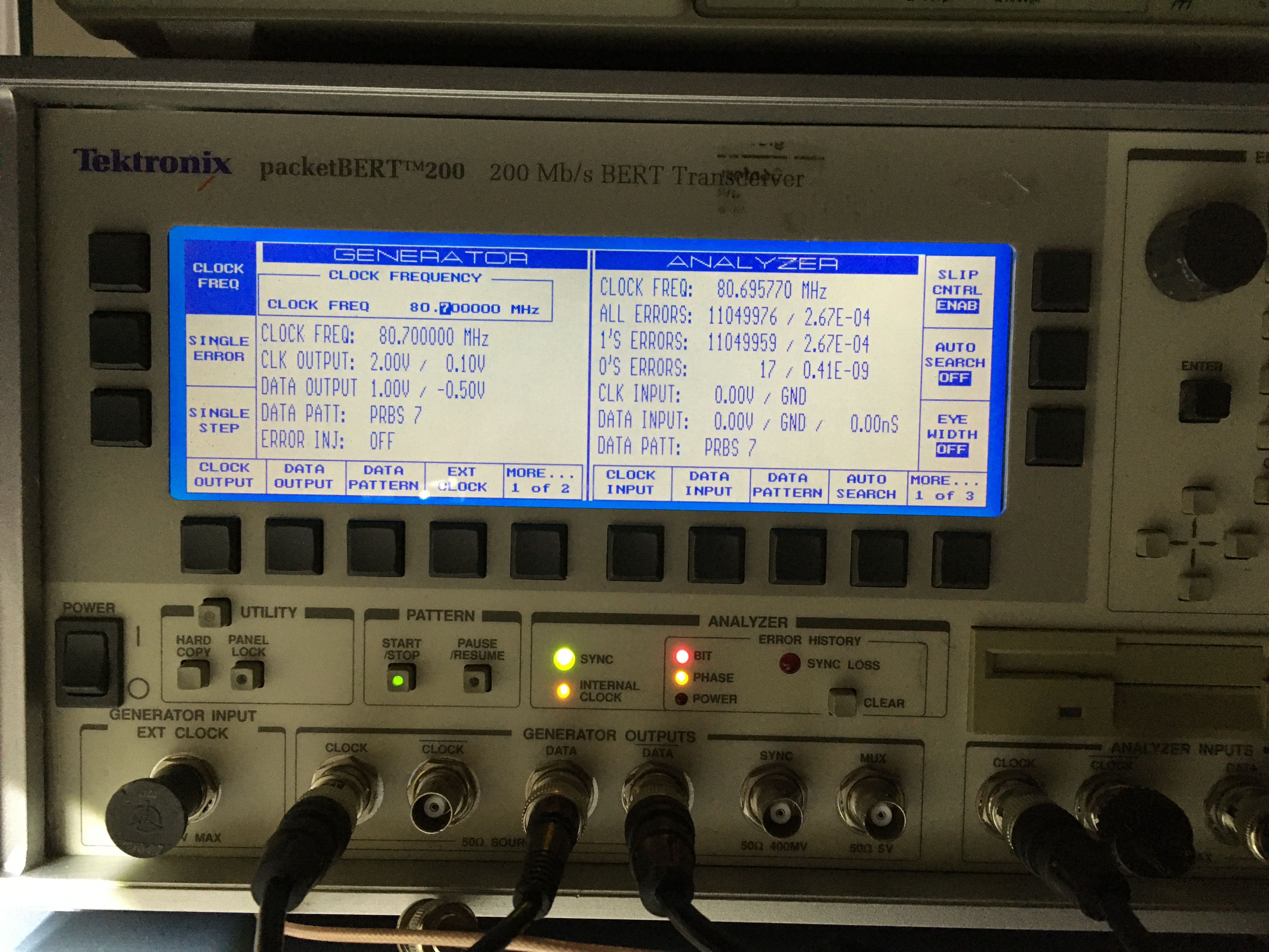 When an error occurs I lower the frequency, and reset the error. And the end
Results of the second test
I could get a max throughput of:
 So it’s very close to 80 Mhz. However in a real case scenario don’t expect to send data across with this high speeds. In reality I ques somewhere around 10 Mhz till 40Mhz is more realistic.
