In part two an ULN2023 is used so we can connect the IV-3A segments to 20V, while driving the segment with 5V. In this part the IV-3A is connected to the ULN2803A, and a 74LS48 which is BCD to 7-Segment Decoder. By using the 74LS48 we can use 4 bits to drive the 7 segments.
Connecting the IV-3A
To connect the IV-3A to the IV-3A follow the following table:
IV-3A connections
IV-3A
ULN2308
5
8
6
7
10
6
1
5
2
4
3
3
4
2
The last connections to make are the grid and heater. The schematic looks like:
IV-3A connections
Connect the 74LS48
The datasheet for the 74LS48 can be found here. Before connecting up the 74LS48, we need to invert the signals. Since the ULN2308 is a NPN Darlington array, we need to invert the signals, so that a segment is activate when the input signal is going HIGH, instead of LOW.
An easy solution is to use a HEX invert. Since a HEX invert, as the name implies has 6 inverters, so we need two of them. So 2x a 74LS04 is going to be used.
The schematic looks like:
Display Driver schematic
When connecting the all the BCD (248) inputs( pins: 76,2,1) to GND, the IV-3A should show a “zero”. Like wise, if we connect these pins to 5V, a 8 is shown. The table below show the BCD coding for the pins:
BCD (248) conversion table
A3
A2
A1
A0
Digit
0
0
0
0
0
0
0
0
1
1
0
0
1
0
2
0
0
1
1
3
0
1
0
0
4
0
1
0
1
5
0
1
1
0
6
0
1
1
1
7
1
0
0
0
8
1
0
0
1
9
In the next article the HP8175A is going to be used as a binary 4 bits counter.
In the first part I mentioned that I used 2 DC-to-DC converters. In this article we’re going to see how these modules are connected, and a ULN2803A is used to connect the segments to 20V, while driving the segments from a 5V rail.
Connecting the DC-to-DC converters
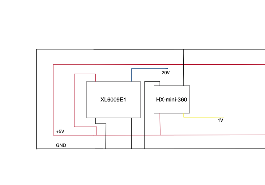
The connection of the DC-to-DC converters is very simple:This simple schematic shows how the modules are connected to the 5V rail.
One the modules are connected, the voltages needs to be set. This is done by turning a potentiometer. The XL6009E1 is set to +/- 20V while the HX-mini-360 is set to 1V.
Connecting the ULN28023
The ULN28023 is a Darlington array. Here you can find the datasheet.
The datasheet mention the following description:
The ULN2803Adeviceis a 50 V, 500 mA Darlington transistor array.The device consists of eight NPN Darlington pairs that feature high-voltage output swith common-cathode clamp-diodes for switching inductive loads.The collector-current rating of each Darlingtonpair is 500 mA. The Darlington pairs maybe connected in parallel for higher current capability. Applications include relay drivers,hammer drivers,lamp drivers,display drivers(LED and gas discharge),line drivers,and logic buffers.The ULN2803A device has a 2.7-kΩ series base resistor for each Darlington pair for operation directly with TTL or 5-V CMOS devices
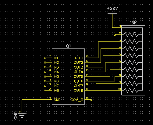
So this IC is perfect to drive the VFD tube. Connecting the ULN2803 is simple:
In The next article the VFD tube is connected, and a 74LS48 is used to drive the the tube.
I got my hands on four IV-3A VFD tubes. When I started to learn about these tubes, I called them “Nixie tubes”, but that is wrong, very wrong. The more I learned about VFD tubes, the less I called them “Nixie tubes”.
So what is a VFD tube ? Well, VFD stands for: “Vacuum Fluorescent Display” And that is the first big difference with a Nixie tube. A Nixie tube is NOT a vacuum tube, a Nixie tube is filled with a gas (neon gas).
A lot of information on how a VFD tube works, can be found online (and Nixie tubes as well of course). According to Wikipedia:
A VFD operates on the principle of cathodoluminescence, roughly similar to a cathode ray tube, but operating at much lower voltages. Each tube in a VFD has a phosphor coated anode that is bombarded by electrons emitted from the cathode filament.[1] In fact, each tube in a VFD is a triode vacuum tube because it also has a mesh control grid
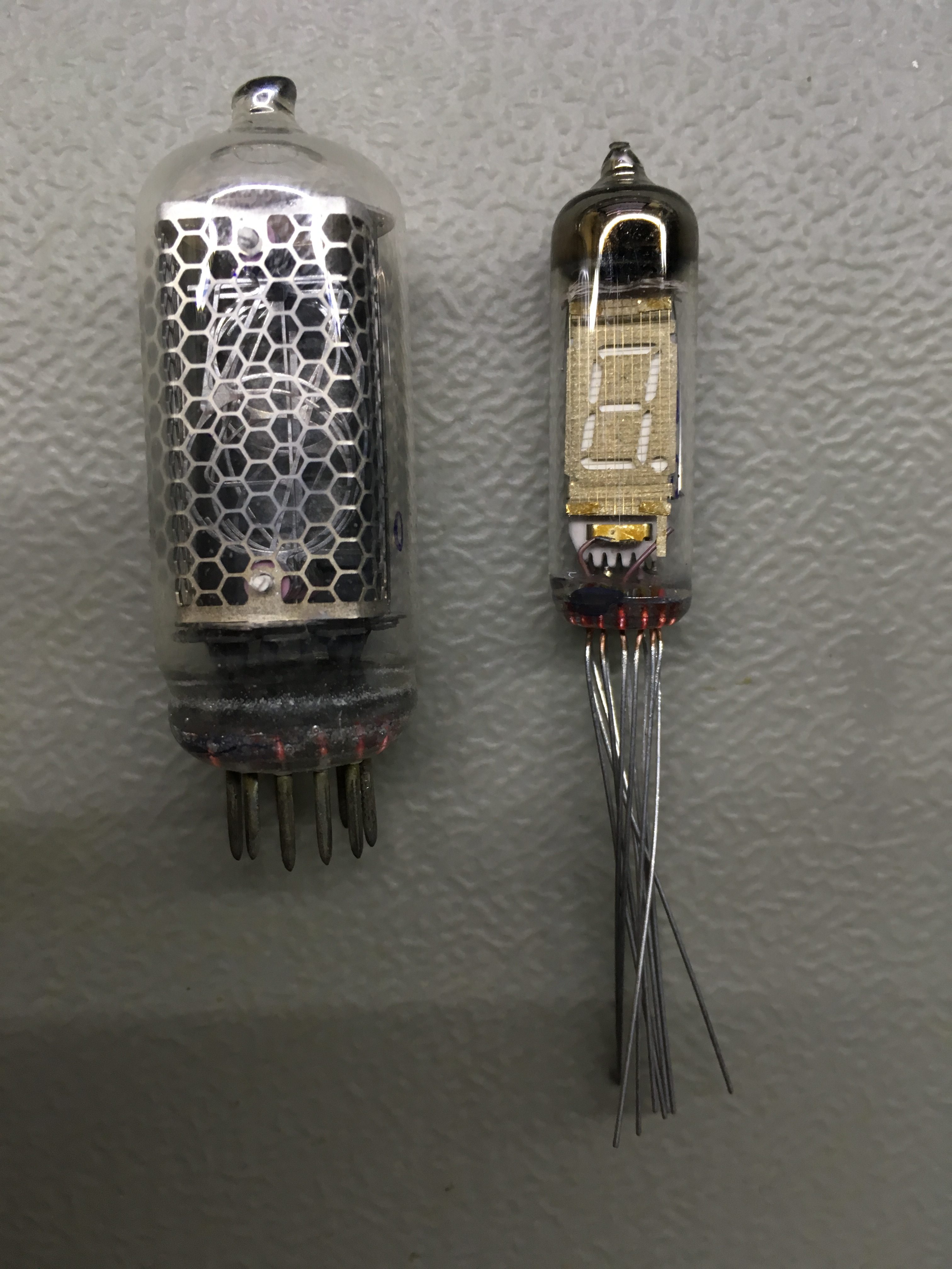
On the left A Nixie tube and on the right a VFD tube
Often I see a VFD display are sold/advertised as being a “Nixie tube” However a VFD display is not a Nixie tube. Compared to a Nixie tube, the Nixie tube has “stacked numbers” (cathodes). And a wire-mesh of anodes. And each number lights up when a high voltage is applied to one of the cathodes.
A Nixie tube works with voltages above 100 Volts (around 180 Volts). A VFD tubes needs multiple voltages for the heater, grid and the segments. The heater voltages are usually around 1V, and the grid and segments are in the range of 20 – 30 Volts.
So a VFD works with much lower voltages then a Nixie tube.
Another difference between a VFD and a Nixie tube is that a VFD is a vacuum tube, whereas a Nixie tube is filled with a neon gass.
Getting the IV-3A tube to work
It took a lot of searching to find information about the IV-3A tube. Since these tubes where produced in Russia, the datasheets for the tubes are also in Russian. And I don’t speak, and cannot read Russian. I did found some info, for instance on the EEVBLOG Forum, where I found the voltages and Amperes needed for the heater. But I could not find information about the pin-out of the IV-3A tube. What I could find, is that the pin-out is the same as the IV-6 VFD tube.
A good friend of mine, Dave gave me an excellent tip: to use the Google translate app, and scan the PDF with my phone’s camera. This worked to some extend. The translation was not perfect, but gave me the last pieces of information I needed to get the IV-3A tube working.
The technical specs of the IV-3A tube
The IV-3A tubes needs the following voltages:
Heating voltage: 0,7 … 1 V
Grid voltage: 20 … 30 V
Anode-segments voltage: 20 … 30 V
Current of heating: 25 … 35 mA
Grid current: no more than 12 mA
Current of the anodes-segments: no more than 0.45 mA
Readiness time: not more than 0.2 s;
The pinout of the IV3A is simple: There is a wire cut off. This wire also has no internal connections. This wire is the “index wire” This is pin 12. Pins 7 and 8 are the heather (cathode). One of these pins must be connected to gnd, and the other pin must be connected to a positive voltage (0.7 .. 1V).
Pin 9 is the grid pin, this pin must be connected to 20 .. 30V. The rest of the pins are the different segments (so pins 1,2,3,4,5,6,10,11) When these pins are connected to 20..30V a segment lights up. When a segment pin is connected to GND, the segment is “off”.
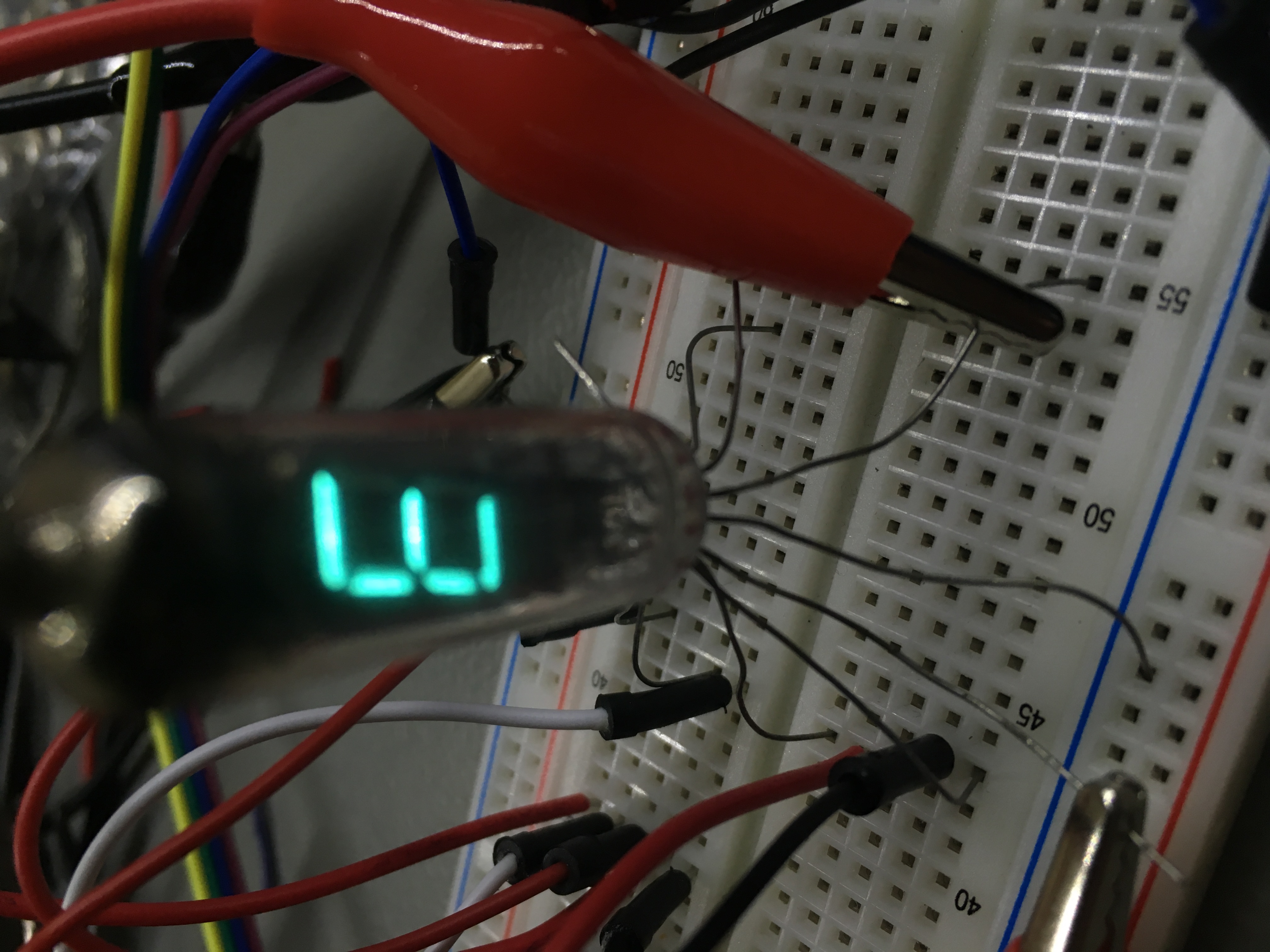
So to connect the IV3-A tube, and to test if all segments work, connect pin 7 to gnd, and pin 8 to +0.7V. Next connect pins 1,2,3,4,5,6,10,11 and pin 9 to +20V (don’t apply the max voltage of 30V to long, this will shorten the life of the tube). If the tube is working you should see all the segments lit.
See the datasheet of the IV-3A here (this PDF is part of Dieter’s Nixie- and display tubes data archive datasheet of the IV-3A
By continuing to use the site, you agree to the use of cookies. more information
The cookie settings on this website are set to "allow cookies" to give you the best browsing experience possible. If you continue to use this website without changing your cookie settings or you click "Accept" below then you are consenting to this.