Using a VFD IV-3A tube to build a simple counter – Part two

Introduction

In the first part I mentioned that I used 2 DC-to-DC converters. In this article we’re going to see how these modules are connected, and a ULN2803A is used to connect the segments to 20V, while driving the segments from a 5V rail.

Connecting the DC-to-DC converters

The connection of the DC-to-DC converters is very simple:
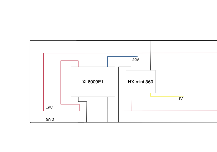
This simple schematic shows how the modules are connected to the 5V rail.

One the modules are connected, the voltages needs to be set. This is done by turning a potentiometer. The XL6009E1 is set to +/- 20V while the HX-mini-360 is set to 1V.

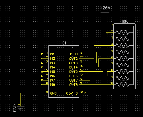
Connecting the ULN28023

The ULN28023 is a Darlington array. Here you can find the datasheet.

The datasheet mention the following description:

The ULN2803Adeviceis a 50 V, 500 mA Darlington transistor array.The device consists of eight NPN Darlington pairs that feature high-voltage output swith common-cathode clamp-diodes for switching inductive loads.The collector-current rating of each Darlingtonpair is 500 mA. The Darlington pairs maybe connected in parallel for higher current capability. Applications include relay drivers,hammer drivers,lamp drivers,display drivers(LED and gas discharge),line drivers,and logic buffers.The ULN2803A device has a 2.7-kΩ series base resistor for each Darlington pair for operation directly with TTL or 5-V CMOS devices

So this IC is perfect to drive the VFD tube. Connecting the ULN2803 is simple:

In The next article the VFD tube is connected, and a 74LS48 is used to drive the the tube.

Using a VFD IV-3A tube to build a simple counter

Introduction

Some time ago I figured out the pins of of IV-3A VFD tube. In the upcoming articles series I’m going to build a simple counter, and planning to use some of my LAB equipment to test and build this counter. Just for fun.

Roughly I’m thinking of planning the following articles :

      • Implement the PSU for the different voltages (1V,5V,20V)
      • Design and implement the display driver
      • Use the HP 8175A to simulate a 4 bit binary counter
      • Using a Hp8110A as a serial data generator to simulate a 4 bit counter
      • Finally build the counter

Implement the PSU for the different voltages (1V,5V,20V)

One of the first challenges when working with a VFD tube is getting all the different voltage rails required. The IV-3A tube needs the a couple of voltages: 1V,5V,20V

The get the 5V rail is not a real problem, 1V and 20V can be more difficult.

To start with the 1V rail, one might think of a simple voltage divider, but this is not as simple as it sounds. When trying to drive the heaters, this will add a load to the voltage diver. Which lowers the voltage, resulting in a voltage which is to low. This could be addressed by adding a opamp, as a buffer. However the circuit is going to get more and more complex.

So in this design I’m going to use small DC-to-DC converters. Or step-up converts to be more precise. And I use two modules:

      • One module to step up the voltage to 20v
      • One module to down convert the voltage to 1V

The modules ‘m going to use are:

      • XL6009E1
      • HX-mini-360

These modules are cheap, and easy to use.

The downside to this is that the heater could be driven “to hard”, on the other hand, these tubes can take somewhat of a “punishment”. I’ll keep the rest of  the voltages low by driving the tube with 20V instead of the max 30V.

Both of the DC-to-DC converter modules are driven from a 5V supply. This makes it easy to implement the modules.

In the next article the display driver is going to be implemented.