Introduction
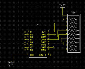
In the first part I mentioned that I used 2 DC-to-DC converters. In this article we’re going to see how these modules are connected, and a ULN2803A is used to connect the segments to 20V, while driving the segments from a 5V rail.
Connecting the DC-to-DC converters
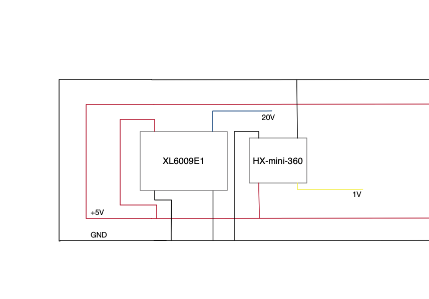
The connection of the DC-to-DC converters is very simple: This simple schematic shows how the modules are connected to the 5V rail.
One the modules are connected, the voltages needs to be set. This is done by turning a potentiometer. The XL6009E1 is set to +/- 20V while the HX-mini-360 is set to 1V.
Connecting the ULN28023
The ULN28023 is a Darlington array. Here you can find the datasheet.
The datasheet mention the following description:
The ULN2803Adeviceis a 50 V, 500 mA Darlington transistor array.The device consists of eight NPN Darlington pairs that feature high-voltage output swith common-cathode clamp-diodes for switching inductive loads.The collector-current rating of each Darlingtonpair is 500 mA. The Darlington pairs maybe connected in parallel for higher current capability. Applications include relay drivers,hammer drivers,lamp drivers,display drivers(LED and gas discharge),line drivers,and logic buffers.The ULN2803A device has a 2.7-kΩ series base resistor for each Darlington pair for operation directly with TTL or 5-V CMOS devices
So this IC is perfect to drive the VFD tube. Connecting the ULN2803 is simple:
In The next article the VFD tube is connected, and a 74LS48 is used to drive the the tube.
