Introduction
In part two an ULN2023 is used so we can connect the IV-3A segments to 20V, while driving the segment with 5V. In this part the IV-3A is connected to the ULN2803A, and a 74LS48 which is BCD to 7-Segment Decoder. By using the 74LS48 we can use 4 bits to drive the 7 segments.
Connecting the IV-3A
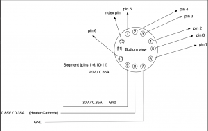
To connect the IV-3A to the IV-3A follow the following table:
IV-3A connections
| IV-3A | ULN2308 |
| 5 | 8 |
| 6 | 7 |
| 10 | 6 |
| 1 | 5 |
| 2 | 4 |
| 3 | 3 |
| 4 | 2 |
The last connections to make are the grid and heater. The schematic looks like:

Connect the 74LS48
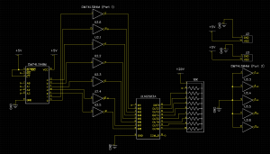
The datasheet for the 74LS48 can be found here. Before connecting up the 74LS48, we need to invert the signals. Since the ULN2308 is a NPN Darlington array, we need to invert the signals, so that a segment is activate when the input signal is going HIGH, instead of LOW.
An easy solution is to use a HEX invert. Since a HEX invert, as the name implies has 6 inverters, so we need two of them. So 2x a 74LS04 is going to be used.
The schematic looks like:

When connecting the all the BCD (248) inputs( pins: 76,2,1) to GND, the IV-3A should show a “zero”. Like wise, if we connect these pins to 5V, a 8 is shown. The table below show the BCD coding for the pins:
BCD (248) conversion table
| A3 | A2 | A1 | A0 | Digit |
| 0 | 0 | 0 | 0 | 0 |
| 0 | 0 | 0 | 1 | 1 |
| 0 | 0 | 1 | 0 | 2 |
| 0 | 0 | 1 | 1 | 3 |
| 0 | 1 | 0 | 0 | 4 |
| 0 | 1 | 0 | 1 | 5 |
| 0 | 1 | 1 | 0 | 6 |
| 0 | 1 | 1 | 1 | 7 |
| 1 | 0 | 0 | 0 | 8 |
| 1 | 0 | 0 | 1 | 9 |
In the next article the HP8175A is going to be used as a binary 4 bits counter.