I started to measure and test several components, and found some diodes which where shorted. Replaced them. However I could not measure any voltages after the full bridge rectifier. Some components are mounted on large heat-sinks. Removing them to get access to the components and be able to read the markings or to test them out of circuit, would be a pain.
Fighting with this power supply for a couple of evenings, I decided to take another route. In the meantime the alternative PSU was delivered. After comparing both the PSU’s together I noticed that only one voltage rails was different.
Modifying an PSU
Since fixing the primary side of the PSU would be very difficult to do, I started to look at the secondary side. Both the PSU’s are from the same series. So I figured the manufacturer probably used a couple of zener diodes, and resistors to control the output voltage. So I started to swap out diodes and resistors which where different and which I could relate to the voltage rail I wanted to adjust.
The moment of truth
I powered to PSU up, and measured all the good voltages (they where a little higher, but that’s okey since no load is attached.). I decided to go for it, and placed the PSU on top of the chassis, so I could test the PSU without going through the rather complex method of installing the PSU.
And after connecting the main power, and flipping the power switch, the PB200 came back to live.
A few quick tests showed me that the generator and analyzer are working without any problems. And I refitted the PSU back into the PB200.
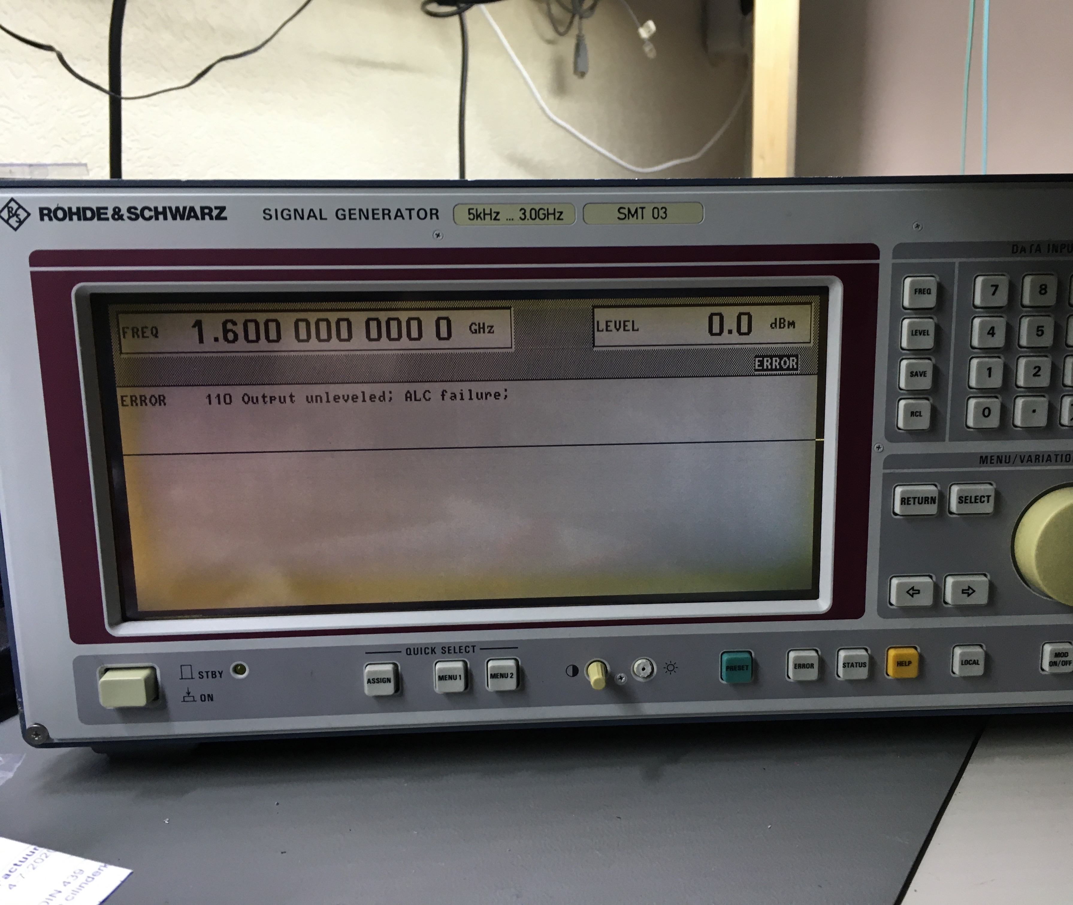
The R&S SMT03 is a RF signal generator which can generate signals from 5Khz up to 3Ghz, while the signal level can be from -144dBm to +13dBm with 0.1dBm resolution.
Signal generators like the SMT03, and other (for example the HP ESG series like the E4421B) are mainly used to test communication devices and a like. Signal generators like this, are not arbitrary signal generators (however they may have an option to generate LF (Low Frequency) signals like square, sine, sawtooth wave-forms.
RF Signal generators generate sinus signal, and can generate different modulations (FM,PM,AM etc). These signal generators are a specialized piece of equipment.
An R&S SMT03 with problems
The SMT03 I’ve got in the LAB has some problems:
A few lines are visible on the LCD screen
When the unit is on for some tine, above 1.8Ghz the error: 110 Output Unleveled ALC failure is displayed .
The lines on the LCD screen are somewhat annoying, they don’t influence the working of the unit. The ALC Unleveled error does. When I try to measure the signal, the level is all over the place, and has a low level. I noticed that in the short time this error is not present I can loose up to 4dBm when I generate signal above 1.8Ghz.
The challenges
When trying to fix an error like this, it’s important to understand the error. At the time this error presented itself, I didn’t had access to a Service Manual. And from the User manual I didn’t got any wiser. So after some thinking I concluded that ALC must stand for: Attenuation Level Control
This leads me to the conclusion that a possible cause could be a PLL circuit which is unable to establish a successful lock. The bad news is: this may be due to a lot of other problems:
The input frequency may be of, or the signal is to low
Power problem (low / not working power rail
Mixer problem
And a lot of other related problems
Trying to diagnose the problem futher
So to diagnose such a problem, a block diagram and a schematic would be very helpful. But I got neither of them.
Another challenge is that the unit consists of modules, which plug into a back-plane. Operating the modules outside of the unit seems only possible with a “service kit” which I don’t have access to, and cannot find any information about.
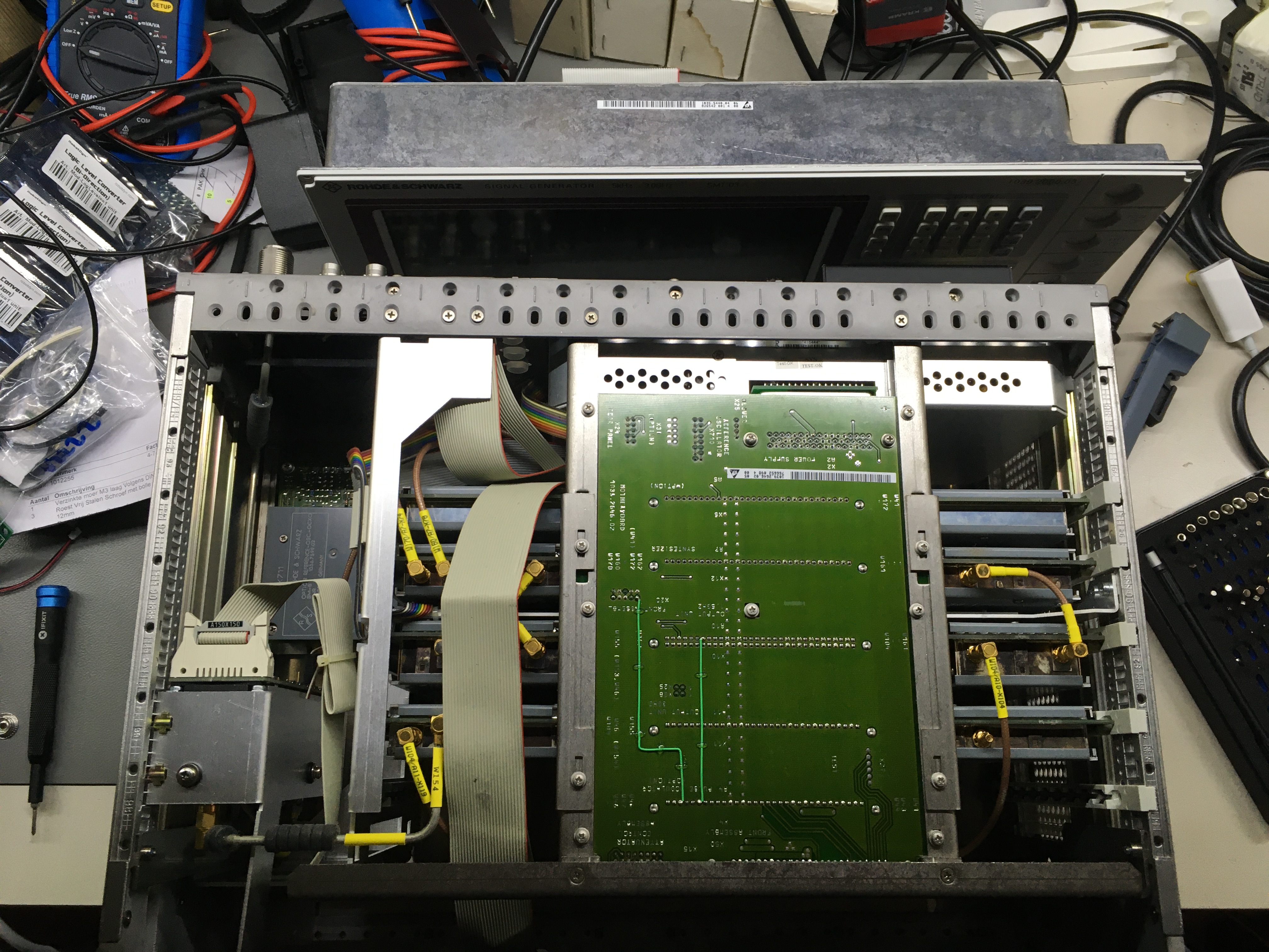
Despite the fact I don’t have the above items, I can observe the error, and take a look at how the physical signal path. So I opened the unit by removing the covers. Which is a simple and straightforward process: By unscrewing the bumpers on the back of the unit the top and bottom covers come off.
R&S SMT03 on the inside
Tracing from the output connector the signal path back I noticed that:
From the output connector, the signal is going through an attenuator, and then straight into a 3Ghz module (W154).
From the 3Ghz module the signal is entering an 1.5Ghz module (W104).
From this module the signal is going to a synth module, and a signal generator module.
And this tells me that the 3Ghz module has some kind of “pass-through”, so that signals up to 1.5Ghz are passed through the 3Ghz module (not sure at this point if some additional filtering is done). When signals are above 1.5Ghz the 3Ghz module generates the frequencies from 1.5 till 3Ghz.
This could mean that the ALC Unleveld error is somewhere in the 3Ghz module. Which means I could leave all the other modules alone.
For a moment I was thinking about a possible power rail problem, however this is most unlikely, since I aspect that for every frequency the ALC Unleveled error should be displayed, or that other errors would pop-up.
To summarize
Working on these units is not easy
A Service manual would be a great help
In [part 2] I’m going to try to repair this R&S SMT-03
By continuing to use the site, you agree to the use of cookies. more information
The cookie settings on this website are set to "allow cookies" to give you the best browsing experience possible. If you continue to use this website without changing your cookie settings or you click "Accept" below then you are consenting to this.