Introduction
Almost every electronics lab equipment has the possibility to be controlled remotely. This is almost always done by using IEEE-488. Also known as ” HP-IB” As HP called it when HP developed this 8 bit parallel bus. It’s also know as “GPIB”. (General Purpose Interface Bus).
In the old days a dedicated computer card was used as a controller, to perform remote operations on the lab equipment.
Nowadays we have LXI for example, making it possible to remotely control devices over Ethernet network by using the TCP/IP protocol. This doesn’t mean GPIB isn’t used anymore. Even modern equipment can have a IEEE-488 interfaces. For example my Rigol DM3608 has a IEEE-488 interfaces and can be configured to understand a specific command set.
Use an IEEE488(GPIB) communication -adapter
Nowadays it’s more common to use USB GPIB controllers to remotely control the (old) lab equipment. There are a couple of choices:
- Use Prologix GPIB-USB
- Use an IEEE488(GPIB) communication -adapter (Keithley or National Instruments for example)
- These adapters may also be available as Ethernet controllers which plug into a LAN network.
However there are mainly two difference between the “brand names” and the Prologix:
For example the National Instruments (NI) USB controller present itself as a GPIB device. Whereas the Prologix presents itself as a serial device.
Which one to choose ?
If you look at the known brand names one, presenting them self as a gpib device, you notices these devices are not cheap. A new adapters can cost you as much as $1300,00 and no.. this is not a typo. While the Prologix adapter cost around $150,00 dollars.. So what’s the catch ? (there is always a catch).
And as always: It’s depends. Say for instance that you want to use an application from a vendor which only works with a GPIB device. The Prologix in this case won’t work. At least not out of the box.
On the other hand: If you’re about to write your own data log / measure applications, the Prologix might be a perfect solution, since it’s a serial device, and you don’t have the overkill of using the NI-VISA drivers (for example)
Then there is of course the price. Luckily the GPIB USB adapters can be found relatively cheap second hand. I did found a genuine NI GPIB USB-HS new in box for a around $150,00 dollar. Which brings these adapter in the price range of the Prologix one.
Comparing a Prologix and a NI GPIB USB-HS adapter
Since I have both types, let’s compare them in practice. To compare the adapters i’m going to use them in the following scenarios:
- Using the adapters with a existing application from a vendor (Rohde Schwarz WINIQSIM) which is a Windows application
- Use both adapters to write a own application, testing Windows 10 operating system and MacOS (10.14.6)
Prologix adapter
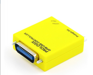
The Prologix USB adapter can be programmed by sending commands through a serial terminal. The GPIB address of the device can be set by sending:
++addr #
So for example to set the GPIB address to ‘8’:
++addr 8
There several commands, which allows to configure the adapter to one needs. Also it’s possible to update the firmware. To talk to the adapter FTDI device drivers are needed, which are available for Windows, Linux and MacOS.
The national Instruments (NI) GPIB-USB HS adapter
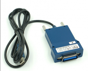
The NI adapter needs NI-VISA drivers to be installed. These drivers are available for Windows, Linux and MacOS.As far that I know there is no firmware available for these adapters. There is a lot of information about how to install NI-VISA drivers etc. The only thing I needed to was to install the NI-VISA software, and plug in the adapter.
Using existing application WinIQSIM
T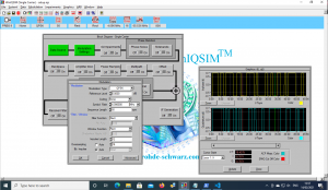 he application WinIQSIM works perfectly with the NI USB-GPIB-HS. The application has the benefit of using a GPIB device, or serial. However I could not get a serial device to work with my Rohde Schwarz AMIQ. I either received a timeout, or a communication error. At the end I tried to use a null modem cable, but this gives me problems also.
The main problem when using the Prologx in the case is the speed setting. The applications “sweeps” the baud-rate setting. The Prologix however, doesn’t care about serial baud setting. So the WinIQSIM application gets confused, when trying to determine the baud settings. I tried several options, even disabling the “sweep”, however the application kept trying to find the highest speed it could communicate on.
It might be possible to implement a driver in NI-VISA, I didn’t test this however.
In this case: The NI USB adapter wins.
Writing my own application
In this test I’m going to test the python script which I wrote to remotely control my HP 8175A. In this case I’m going to use Python since this makes testing under MacOS and Windows 10 very easy.
I’m going to use two modules:
On both systems I’m using virtual environments.
Test under MacOS
And this test ended very quickly.. I tried to use PyVisa under MacOS, and couldn’t get PyVisa to work. The library isn’t listing my GPIB device. I tried installing several versions of NI-VISA library. I even tried different version of NI-488.2 drivers.
>>> import pyvisa >>> rm = pyvisa.ResourceManager() >>> rm.list_resources() ('ASRL/dev/cu.Bluetooth-Incoming-Port::INSTR', 'ASRL/dev/cu.EEsiPhone-WirelessiAPv2::INSTR') >>>
Update: I finally got the NI-VISA driver working under MacOS. I just reinstalled the drivers, and when I give the path to the library (I tried that before, which didn’t work) it works:
>>> import pyvisa
>>> rm = pyvisa.ResourceManager('/Library/Frameworks/VISA.framework/VISA')
>>> rm.list_resources()
('GPIB0::8::INSTR', 'GPIB0::9::INSTR')
>>>
When I use the NI-VISA tools, the adapter is recognized without problems.
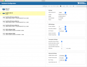
Test under Windows 10
So I moved to windows, installed NI-VISA library, and PyVisa and it worked instantly. No problems what so ever.
Next I tried pySerial on both platforms, and both worked just fine. Of course I needed to adapt the device name (under MacOS this is:
ser = serial.Serial('/dev/cu.usbserial-PX4UALP2')
Under Windows this is:
ser = serial.Serial('COM4')
The whole python script:
import serial

cmd = ['RST','DM0;DUR0,1s;IFM(CLOCK),,,1111','DM1;CFM(CLOCK);TSA0;CHD0,(CLOCK),0000,0001,0010,0011,0100,0101,0110,0111,1000,1001;TSA9;CHD0,(END)','PM0;CD;(PROG1);CR7;CE;(END)','OM;POD 1','CM 0;CYM 1','UP;SA','LO']

ser = serial.Serial('/dev/cu.usbserial-PX4UALP2')

for c in cmd:
   send_cmd = c+'\n'
   ser.write(send_cmd.encode())

ser.close()
Conclusion
When using software which requires a GPIB device, then the easiest option is to chose for a USB controller which present itself as such a device. With some patience these devices can be bought relativity cheap. It might be possible to develop a own NI-VISA (or alike) driver for a Prologix USB adapter. Since I’m no expert in this, I didn’t do any research.
When using a NI USB GPIB controller (or alike) this will work under Windows. Under other Operating systems this might be problematic. With a lot of searching, and trying it might result in a working solution. I couldn’t get the pyvisa to work under macOS the first time, after lot of trying and finally a reinstall, I could get it to work.
In my case the Prologix as the NI GPIB HS works on both platforms.
So the big question is: which wins ? Well if I only had Windows running as my Operating System, I definitely would go for the NI USB GPIB HS adapter, despite of the overkill of the whole NI-VISA environment.
And now that the NI adapter also works under macOS, I prefer the NI adapter over the Prologix adapter. Once the NI-VISA library works, it’s very easy to interact with the device. If however the NI-VISA lib doesn’t work.. or you simply don’t want the overhead the Prologix adapter might be the way to go, while keeping in mind when using vendor supplied software which relies on GPIB controller, the Prologix might not work..
Another thing to consider when using an adapter which relies on drivers like NI-VISA is when transferring software to other systems. For example when you write this awesome script in python for a specific device. When uploading this script to GitHub for others to use it, they need to install the (external) library. Which may be undesirable. In my case this is not really a concern.
However since I got both adapters.. I have the best of both worlds 🙂
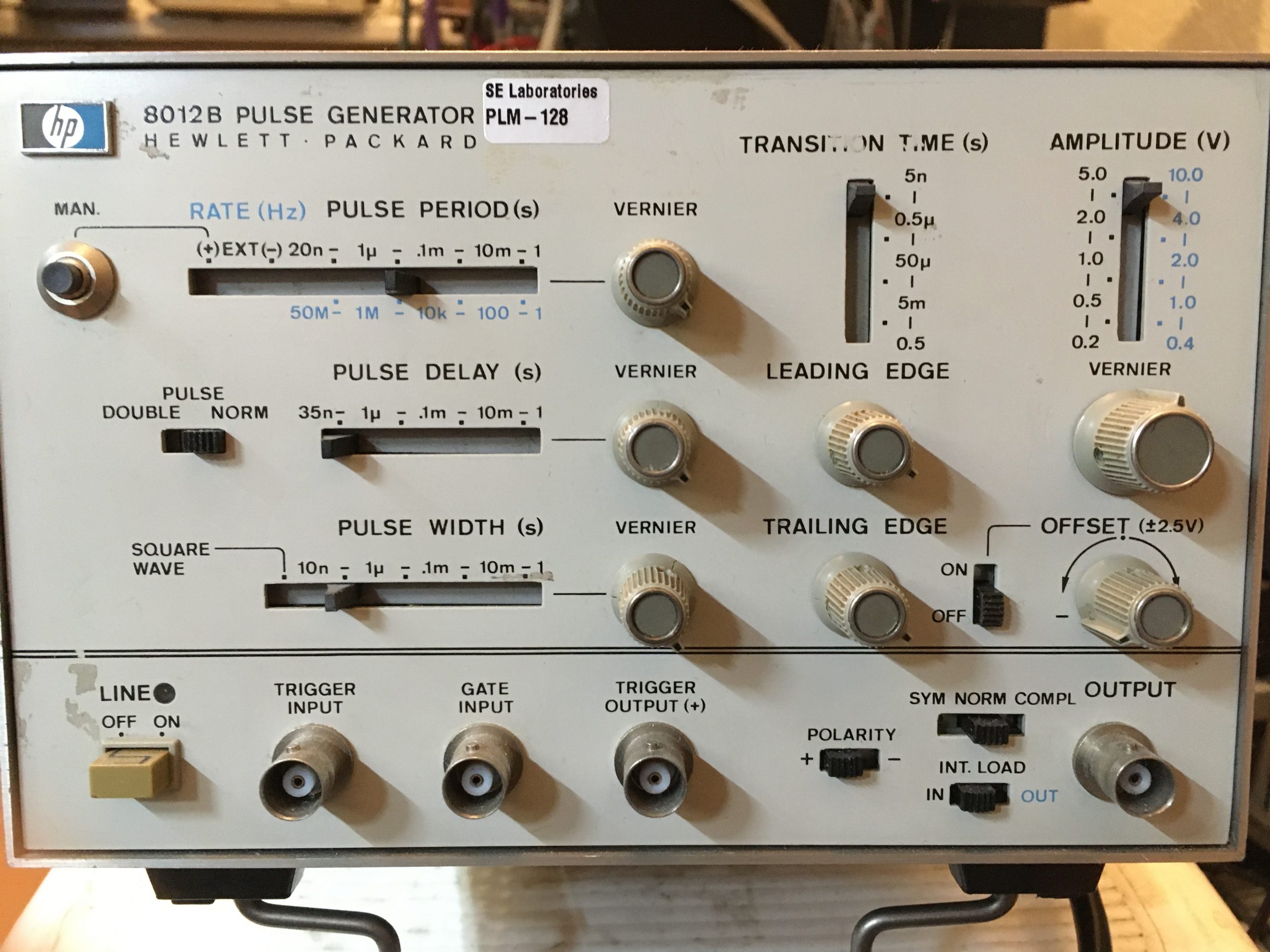 I’ve bought a HP 8012B Pulse generator. The main purpose is to have a small device which I can use for generating clock signals. However the device I received needs some work. The buttons are sticky, and very intermittent. And I also notice that the transformer got really hot while operating the device. However the device produces some signals, since the buttons are intermittent, it’s kind of hard to get some useful signals.
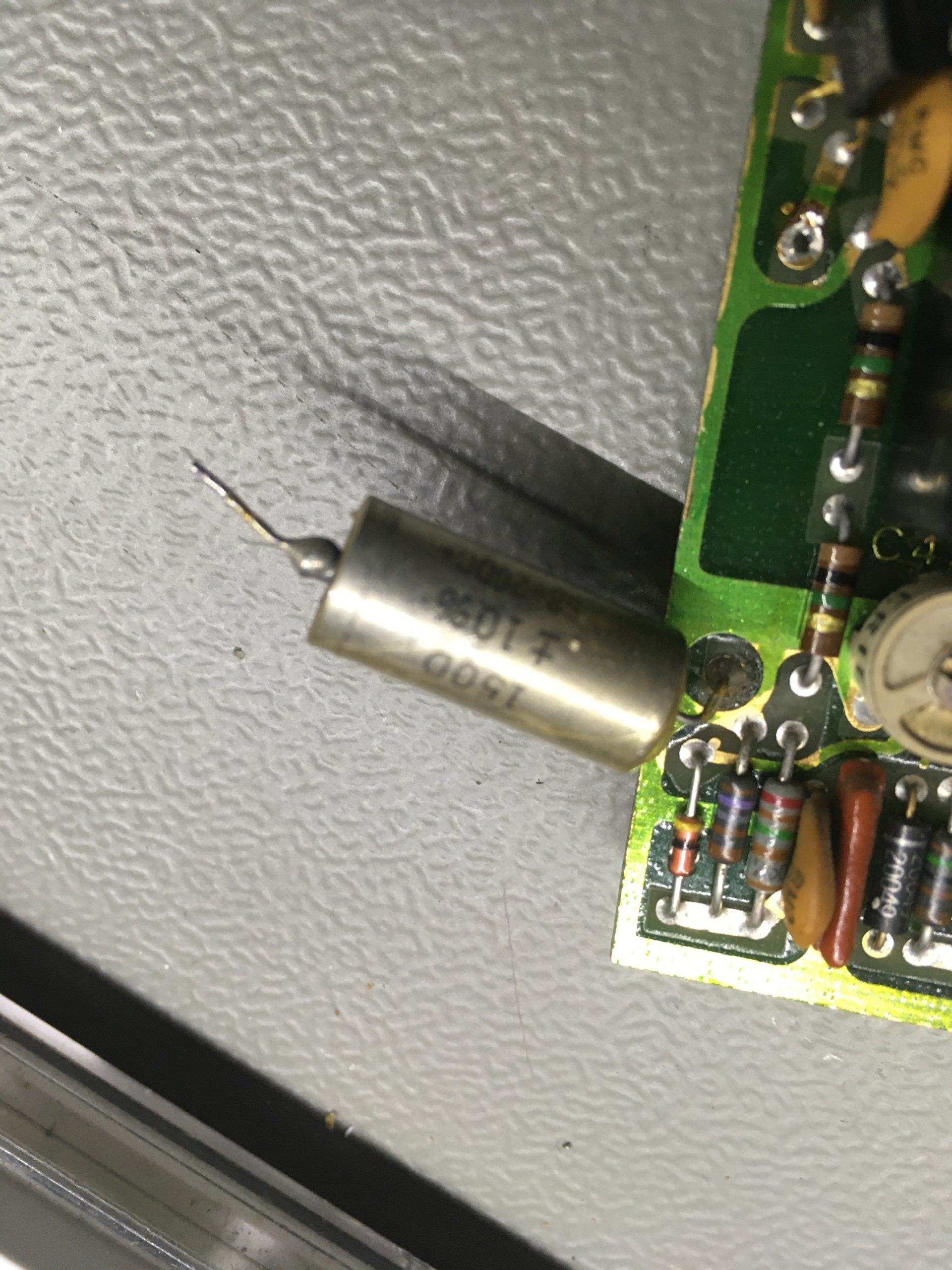 I suspect that the transformer is getting hot, due to some capacitors which gone bad. Before removing the electrolytic capacitors, make pictures. Because there are no markings for the plus or minus on the boards. I tested a few capacitors with my trusty HP 4261A LCR Meter, and found quite a few which are bad. So I decided to replace every electrolytic capacitor. I also check a few resistors, but they where in spec, so no need to change them.
 I started to reassemble the device again. This is also not as easy as it sounds. A few wires from the transformer needs to be soldered onto the board, and since the transformer is heavy and bolted onto the back plate this means I have to keep the back plate somewhat in place, and solder on the wires, without burning anything with my hot solder iron.
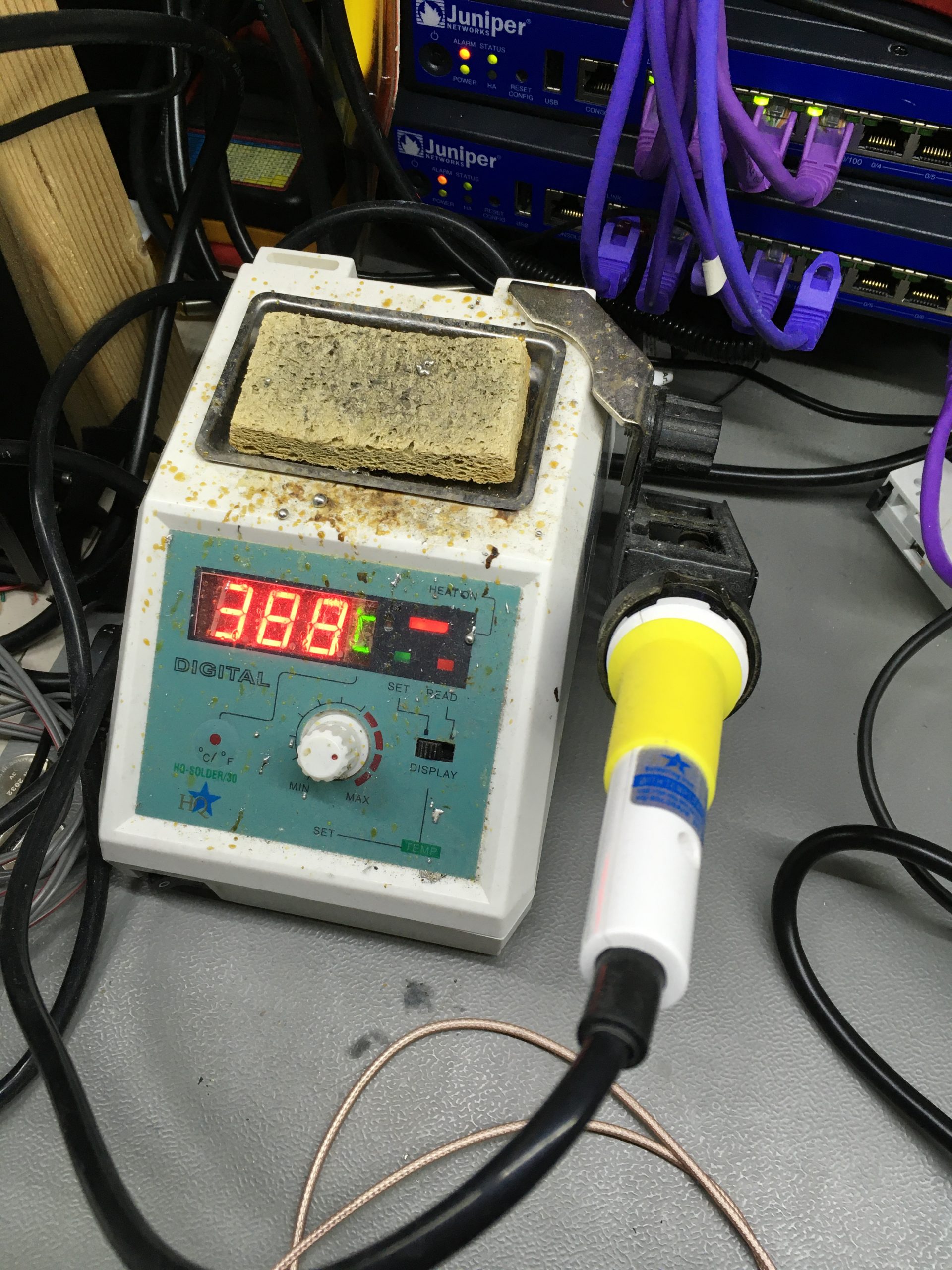
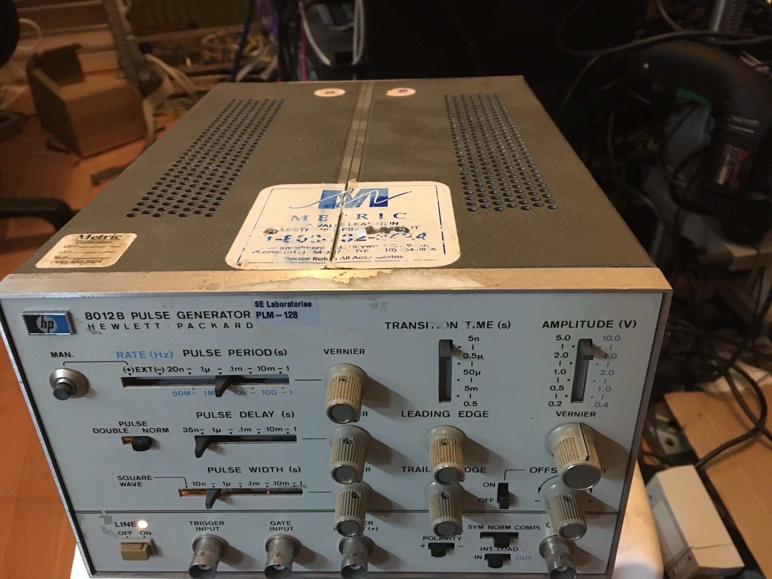 The power on light was burned out, so I needed to replaced this as well. Ideally you need to take the front panel off, or if the device is taken apart, replace the bulb at that time. Since I forgot to do that I have to take the whole thing apart again. Which I really don’t want to do. So I decided to try to place the new light bulb in place with the front cover attached. That’s not easy to do but I managed it.

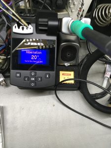 I looked around for a good replacement, taking the requirements into account. And finally came to the conclusion it’s better invest more money, then trying to save some money and go for a cheaper solution, by looking into clones. So I bite the bullet, and decided to go for a JBC station. These stations are not cheap, but in every test I have seen, the JBC just leaves all the others behind in terms of performance. Furthermore I looked for example at Hakko stations, but the don’t have a small footprint. Well they have a large order of different tips, the JBC even has more choice. Also the operation experience is better on the JBC.
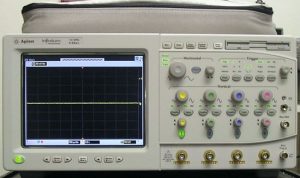
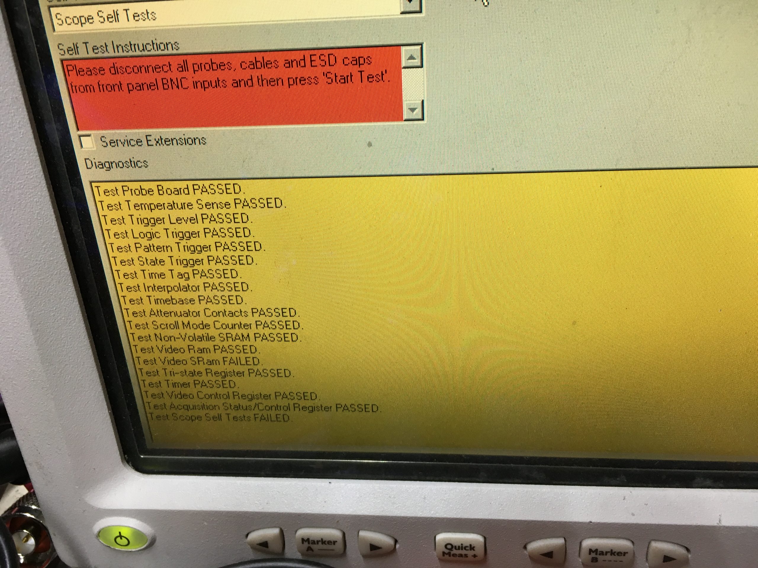
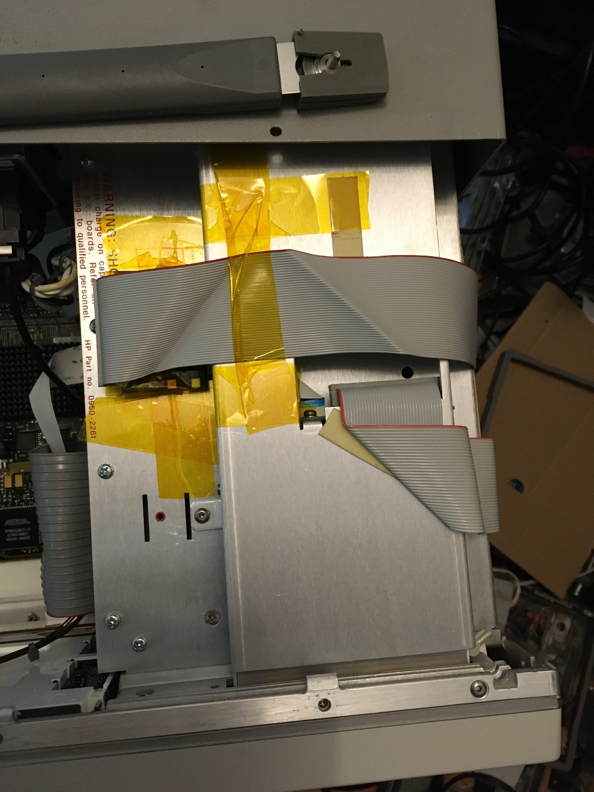
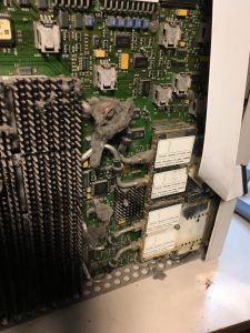 So maybe the card has bad contacts, so I decided to remove the case, and take a look inside. And that is when I noticed a lot of dirt. I have seen dirt in machines, but this is really bad. I cleaned most of it. Cleaned the A6 board, and sprayed some Deoxit on the contacts. and reinstalled the board. Unfortunately, the problem stayed.
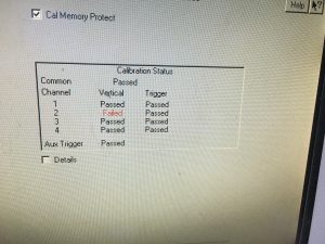 I went ahead and tried to calibrate the scope by using the self calibration process. This is a straight forward process. It only takes some time to complete.